
Headlights
On cars VAZ-2105, VAZ-2104, rectangular headlights are used, combined with direction indicators into one unit - a block headlight. In the lower part of the optical element of the headlight there is also a side light lamp.
The scheme for switching on the headlights of VAZ-2105 and VAZ-2104 cars is shown in fig. 241. The dipped and main beam headlights are switched on using the auxiliary relays P5 and P6 located in the mounting block 2. The control voltage to the relay windings is supplied from the headlight switch 4 (located on the steering column), if the switch key 5 for outdoor lighting is fully pressed.
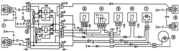
Pic. 241. Scheme for switching on headlights and fog lights on the VAZ-2105:
1 - headlight bulbs; 2 - mounting block; 3 - the switch was lit; 4 - headlight switch; 5 - outdoor lighting switch; 6 - fog light switch in the rear lights; 7 - fog light control lamp; 8 - fog light lamp in the rear lights; 9 - control lamp high-beam headlights; P5 - relay for turning on the high beam headlights; P6 - relay for turning on the dipped headlights.
It is possible to signal the high beam headlights by pulling the headlight switch lever towards you. In this case, voltage is supplied to switch 4 directly from the INT terminal of the ignition switch.
On some cars, a hydraulic headlight corrector is installed. It serves to adjust the angle of the headlights depending on the load on the car. The hydraulic corrector consists of a master cylinder mounted on the instrument panel, slave cylinders mounted on the headlights, and connecting tubes. The cylinders and tubes contain a special fluid that does not freeze at low temperatures.
Outdoor Lighting
The switching circuit on VAZ-2105, -2104 vehicles is shown in fig. 242. Side light, license plate lights 10 and engine compartment lamp 2 are switched on by a two-position key switch 6 for outdoor lighting (voltage is applied to the headlight switch at the same time). Since 1988, a three-position outdoor lighting switch can be installed on cars. In this case, in the middle position of the key, only the exterior lighting is switched on, and when the key is fully pressed, voltage is also applied to the headlight switch.
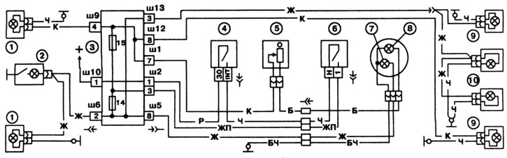
Pic. 242. Scheme for switching on outdoor lighting on a VAZ-2105 car:
1 - side light lamps in the headlights; 2 - engine compartment lamp; 3 - mounting block; 4 - ignition switch; 5 - instrument lighting switch; 6 - outdoor lighting switch; 7 - control lamp for outdoor lighting, located in the speedometer; 8 - instrument illumination lamp; 9 - side light lamps in the rear lights; 10 - license plate light.
In the rear lights in addition to the side light lamps (4 W) There are also fog lights (power 21 W). They can be turned on with switch 6 (see fig. 241) in conditions of poor visibility. Since 1988, switch 6 has been supplied with voltage not from fuse No. 17 of the mounting block, but from the outdoor lighting switch through a separate fuse located in the wires next to the fog light switch.
Direction indicators and alarms
The switching circuit on VAZ-2105 and -2104 vehicles is shown in fig. 243. The right or left side direction indicators are switched on by switch 9. In the alarm mode, switch 5 turns on all direction indicators. The flashing of the lamps is provided by the relay-breaker 6.
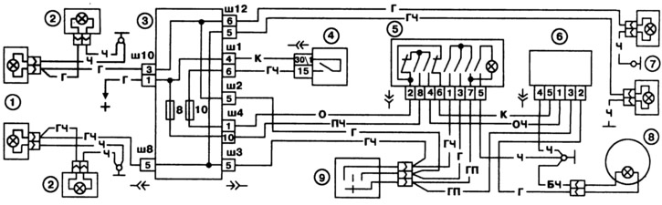
Pic. 243. Scheme of the alarm system and direction indicators on a VAZ-2105 car:
1 - direction indicator lamps in headlights; 2 - side direction indicators; 3 - mounting block; 4 - ignition switch; 5 - alarm switch; 6 - relay-breaker for alarm and direction indicators; 7 - turn signal lamps located in the rear lights; 8 - control lamp of direction indicators, located in the speedometer; 9 - turn signal switch.
Until 1985, a relay-breaker of type 23.3747, assembled on integrated circuits, was used. Since 1985, a relay-breaker 231.3747 has been installed, made on discrete elements. The characteristics of both relay-breakers are the same.
External difference consists in the absence of plug 5 at the relay-breaker 231.3747. Therefore, no brown wire is needed connecting the plug 5 of the relay-breaker to the plug 6 of the alarm switch 5.