
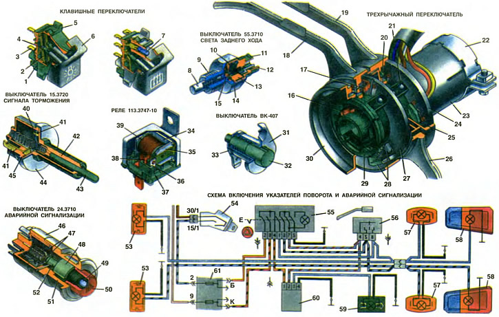
1, 11. Foundation. 2, 10. Movable contact plate. 3, 12. Fixed contact-plug. 4. 15. Pusher. 5, 9. Corps. 6. Key. 7. Lamp A12-1.2. 8. Stock. 13. Spacer. 14. Membrane. 16. Horn switch contact. 17. Sliding contact of the switch of indexes of turn. 18. The lever of the switch of indexes of turn. 19. Headlight switch lever. 20. Windshield washer switch jumper button. 21. Ball retainer. 22. Collar of fastening of the switch. 23. Sleeve. 24. Fixed ring with contacts for the headlight switch, windshield wiper and washer. 25. Jumper button for light signal switch. 26. Switch lever for windshield wiper and washer. 27. Fixed ring with switch contacts for turn indicators. 28. Dogs. 29. Hub. 30. Driving ring. 31. Switch housing. 32. Button. 33. Tip. 34. Relay yoke. 35. Anchor relay. 36. Restrictive stoic. 37. Relay base. 38. Rack connected with a plug «87». 39. Relay coil. 40. Movable contact plate. 41. Fixed contacts-plugs. 42. Rod guide. 43, 48. Stock. 44. Casing. 45. 51. Switch housing. 46. The base of the switch. 47. Contact jumpers. 49. Lamps 12 V 1.1 W. 50. Button. 52. Sleeve. 53. Front direction indicators. 54. Ignition switch. 55. Alarm switch. 56. Turn signal switch. 57. Side direction indicators. 58. Rear lights. 59. Indicator lamp for direction indicators. 60. Relay-breaker for direction indicators and alarms. 61. Fuse box.
Key switches
On cars «Oka» unified key switches of type P147 or 26.3710 are used. They consist of the same, interchangeable parts and differ only in the number of fixed contacts, contact plates, pushers, as well as symbols on the keys. Switches can be divided into two groups. The first group is three-position switches (in the picture on the left), which has three key positions. This includes switches for: exterior lighting, heater, and rear window wiper and washer. The second group - two-position switches with a control lamp (in the picture on the right). These are the switches for the rear fog light and heated rear window. The switches are installed on the instrument panel and are fixed in the socket with the help of spring brackets of the housing. To remove the switch, pull it towards you and overcome the force of the spring clips.
The switch has a plastic case 5, in which a plastic base 1 with fixed contacts 3 is inserted. A key 6 swings on the cylindrical protrusions of the case, having two tubular guides, in which there are pushers 4 with springs. The pushers put pressure on the contact plates 2 and, depending on the position of the keys, press the upper or middle part of the contact plate to the fixed contacts.
For two position switches (in the picture on the right) in the upper part of the housing there is a socket into which a miniature A12-1.2 lamp is inserted, and on the button opposite the lamp there is a hole covered with an orange light filter. These switches have only one contact plate and one pusher.
Reversing light switch
Switch 55.3710 is wrapped in the gearbox housing, and its stem 8 rests against the reverse gear fork (see ch. 20). The plastic base 11 of the switch with fixed contacts 12 and a spacer 13 is rolled in a steel case 9. A rubber membrane 14 is installed between the case and the spacer, insulating the contacts from oil that can penetrate from the gearbox.
In the initial position, the movable contact plate 10 is pressed by a spring from the fixed contacts 12. When the reverse gear is turned on, the plug 7 (see ch. 20) presses on the stem 8 of the switch. The rod, in turn, through the membrane 14 and the pusher 15 presses the plate 10 to the fixed contacts, and they close, including the reversing light lamps in the rear lights.
Three lever switch
The switch type 21011-3709310 is mounted on the steering shaft mounting bracket pipe and fastened to it with a clamp 22.
On the hub 29 of the switch are put on: a driving ring 30, three movable rings with levers 18, 19, 26 and two fixed rings 24 and 27. The rings are held on the hub 29 by a sleeve 23 riveted to the hub 29 with two rivets. The fixed positions of the movable rings are provided by spring-loaded ball retainers 21, which are included in special sockets of the hub 29.
On the moving rings, sliding contacts 17 pressed by springs are installed, closing the fixed contacts mounted on the fixed rings. On the fixed ring 24, in addition, there are two spring-loaded jumper buttons 20 and 25 of the windshield washer and light alarm switches.
If you pull the end of the lever 19 of the headlight switch towards you, then the opposite side of its movable ring will press the button 25 and the light alarm will turn on - the high beam of the headlights. When the lever 19 is released, its movable ring will take its previous position and the spring will press the button 25 from the fixed contacts - the main beam of the headlights will turn off.
The windshield washer switch works in a similar way, in which the tip of button 20 passes through a slot in the ring of lever 19 and abuts against the ring of lever 26. If you pull the end of lever 26 towards you, the movable ring of the lever will press on button 20 and the switch contacts will close - turn on windshield washer motor.
The direction indicator switch has a device for returning the lever to its original position, i.e. for automatically turning off the direction indicators after the turn is completed. The device consists of a driving ring 30 and two pawls 28 mounted on a fixed ring 27. Two cylindrical protrusions of the driving ring 30 fit into the holes of the steering wheel hub, and therefore the driving ring rotates with the steering wheel. Dogs 28 are located in the groove of the ring of the lever 18 of the direction indicators.
When the direction indicators are turned on, the edge of the groove presses on one of the pawls and raises it to a vertical position. In this case, the pawl allows the drive ring 30 to rotate in the direction of rotation, but when the steering wheel returns to its original position, the protrusion on the underside of the drive ring abuts against the pawl and turns it to its previous position. The dog, in turn, presses on the edge of the groove in the lever ring 18 and returns the ring with the lever to its original position - the direction indicators turn off.
Stop signal switch
Switch 15.3720 is mounted on the bracket of the clutch and brake pedals so that the rod 43, on which the plastic buffer is put on, abuts against the special platform of the pedal. Fixed contacts 41 are inserted into the plastic case 45, made in one piece with the plugs. A movable contact plate 40 closing them is pressed against them by a spring. The body, together with the guide 42 of the stem, is rolled in a steel casing 44. The contact plate 40 is pressed from the fixed contacts under the action of a force transmitted through the stem 43.
Relay
Relay type 113.3747-10 is used to turn on the starter and ignition, low and high beam headlights, rear window heating element and to turn on the electric motor of the engine cooling fan. All of these relays are mounted on a bracket behind the fuse box.
On the plastic base 37 of the relay, a yoke 34 with a coil 39 is fixed. The output plugs of the relay are also fixed on the base 37. The outputs of the coil winding are connected to the plugs «85» and «86», and the yoke - with a plug «30». The contact plate of the armature 35 in the normal position is pressed against the limiting post 36. When the relay is activated, the contact plate of the armature closes with the contact of the post 38 connected to the plug «87». The relay operation voltage is not more than 8 V, and the winding resistance (85±8,5) Ohm.
Dome light switch
Switches type VK-407 are fixed with screws on the door pillars. They have a stamped steel body 31 and a plastic button 32 with a metal tip 33 to which the wire is attached. When the button is pressed, the tip moves away from the body 31, and the circuit opens. The same switch, but with a plug rotated 90°, is used to turn on the parking brake warning light.
Hazard switch
On cars «Oka» alarm switch type 24.3710 is used. It is installed on the instrument panel on the left side of the steering column and is held in place by two spring-loaded tabs located on both sides of the switch housing.
The body 51 and the base 46 of the switch are made of plastic and are connected to each other by four latches, which are part of the base and enter the corresponding windows of the body. Plugs and spring contact petals connected to them are riveted to the base. Rod 48 moves in housing 51. Lamp 49 is installed in the rod from the front side, closed with a transparent red button 50. Contact jumpers 47 are fixed on the rod from the rear side and bushing 52 is put on with grooves of a special shape, which includes a pin pressed into the housing. Sleeve 52 is free to rotate on the stem. Its purpose is to hold the rod in the pressed position and release it when pressed again.
When the button is pressed, the switch stem moves, compressing the spring, and the contact jumpers 47 close the contact petals, carrying out the necessary switching. In this case, the end of the pin is hooked on the curly stop of the sleeve 52, and the rod is fixed in the pressed position. When the rod is pressed again, the end of the pin is released from the stop of the sleeve, and the spring returns the rod to its original position. Lamp 49 is used to control the operation of the alarm system. It flashes in sync with the direction indicator lamps after pressing the button.
Relay-interrupter for direction indicators and alarms
The electronic relay-breaker 231.3747 is used to obtain a flashing with a certain frequency of the direction indicator lamps both when the direction indicators are turned on and when the alarm is turned on, as well as to monitor the serviceability of the direction indicator lamps. Relay-breaker 60 is installed under the instrument panel behind the fuse box.
The electronic part of the relay-breaker can be divided into two functional units: a rectangular pulse generator and a lamp health monitoring unit. The generator works both when the turn signal is turned on and when the alarm is turned on. It generates impulses with a frequency of 90±30 min-1, which are fed to the winding of the electromagnetic relay, which is part of the relay-breaker. The contacts of this relay turn on and off the turn signal pumps with the frequency of the generator pulses.
The lamp health monitoring unit works only when the turn signal is turned on and controls the operation of the control pump 59 of the direction indicators located in the instrument cluster. If the direction indicator lamps are in good condition, then the control lamp flashes synchronously and in phase with the direction indicator lamps. If the lamp burned out (21 W) front 53 or rear 58 direction indicator, the control lamp will flash at double the frequency. Pamp burnout (4 W) side direction indicator 57 does not affect the operation of the control pump.