
Headlight adjustment
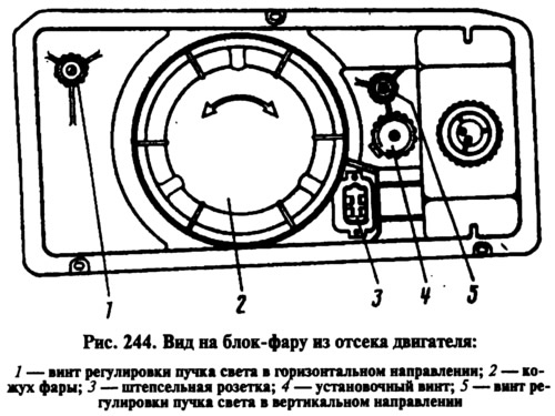
It is carried out by turning screws 1 and 5 (pic. 244), which rotate the optical element in the vertical and horizontal planes. It is most convenient to adjust the headlights with the help of mobile optical devices. If they are not, then the adjustment can be carried out using the screen.
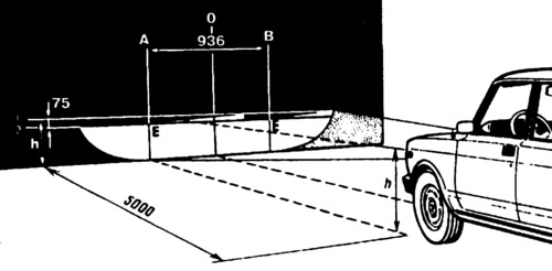
Place a fully fueled and equipped car with a load of 75 kgf on the driver's seat on a flat horizontal area 5 m from a smooth wall or any screen (shield about 2x1 m in size) so that the axis of the car was perpendicular to it. Before marking the screen, make sure that the air pressure in the tires is normal, and then rock the car from the side so that the suspension springs are installed.
Draw on the screen (pic. 245) vertical lines: axial O and lines A and B passing through points E, corresponding to the centers of the headlights. These lines must be symmetrical about the center line of the vehicle. At a height corresponding to the distance of the centers of the headlights from the floor, draw line 1, and below it 75 mm line 2 of the centers of light spots.
Set the headlight hydrocorrector knob on the instrument panel to the zero position (left extreme). If the car is without headlight hydrocorrector, then turn the set screw 4 (see fig. 244) to the far left.
Turn on low beam headlights. Sequentially, first for the right headlight (the left is covered with a piece of cardboard or dark cloth, or turned off), and then for the left (right closed) adjust the headlight beams with screws 1 and 5. For correctly adjusted headlights, the upper border of the light spots must coincide with line 2 (see fig. 245), and the points of intersection of the horizontal and inclined sections of light spots - with lines A and B.
Headlight hydrocorrector
If the headlight tilt angle has increased and the adjusting screw on the headlight unit cannot bring it back to normal, then check for fluid leaks from the hydraulic corrector cylinders or tubes. Remove the slave cylinders from the headlights and check the stroke of the rods, which should be (11±0,5) mm.
The design of the hydraulic corrector is non-separable, and in case of damage it is replaced as a whole assembly with cylinders and tubes. To replace, disconnect the tube clamps from the wire clamps. Remove the handle from the master cylinder and unscrew the nut securing it to the instrument panel. Disconnect the slave cylinders from the headlights and push them with the seal into the car interior. Install the new hydraulic corrector in the reverse order.
Three lever switch
The switch is mounted with a clamp on the steering shaft bracket. Remove the switch in the following order. Remove the steering wheel and then the two halves of the steering shaft cover. Remove the instrument panel and disconnect the switch wires from the vehicle's wire harness. Loosen the mounting clamp and remove the switch. Install the switch in reverse order.
Headlight relay
To turn on the headlights, relays of type 112.3747 or 113.3747 are used, installed in the mounting block. Relay 112.3747 has two fixed contacts, one of which is initially closed with the armature contact. Relay 113.3747 has only one fixed contact, which closes with the armature contact when the relay is turned on. The characteristics of both types of relays are the same. Relay switch-on voltage at temperature (23±5) °С is not more than 8 V, and the winding resistance is (85±8,5) Ohm.
Relay-interrupter for direction indicators and alarms
The relay-breaker is installed under the instrument panel on a bolt welded to the wall of the air intake box. Relay-breakers 23.3747 and 231.3747 must ensure flashing of direction indicator lamps at a frequency of 90±30 cycles per minute at an ambient temperature of -40 to +65°C and a voltage of 10.8 to 15 V.
If one of the direction indicator lamps burns out, then the relay-breaker 231.3747 should double the blinking frequency of the indicator lamp. The relay-breaker 23.3747 in this case creates a constant burning of the control lamp, without blinking.