




Technical specifications
The steering gear is a worm gear with a globoid worm on ball bearings and a double-ridge roller on needle bearings. The gear ratio is 16.4.
Steering gear - symmetrical with three transverse rods (one middle and two outer), a steering knuckle, a pendulum arm and levers on the steering knuckles of the wheels. The outer transverse rods are symmetrical and independent for each wheel.
The maximum force on the steering wheel when turning on the spot on a smooth plate is 25 kgf.
Free play of the steering wheel is no more than 5° (18-20 mm along the rim).
The steering is trauma-safe and has an anti-theft device.
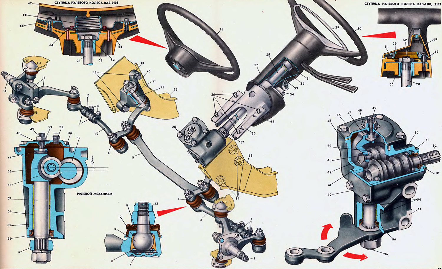
Open large image in new tab »
1. Tightening clamp. 2. Left steering knuckle. 3. Leftmost rod. 4. Pilot arm. 5. Middle rod. 6. Pendulum arm. 7. Tip thrust washer. 8. Conical spring. 9. Ball joint pin. 10. Insert. 11. Protective cover. 12. Pin fastening nut. 13. Rightmost rod. 14. Right steering knuckle. 15. Pivot arm. 16. Adjusting sleeve. 17. Tightening bolt. 18. Bracket fastening bolt. 19. Bracket. 20. Axle washer. 21. Sealing sleeve. 22. Pendulum arm axle. 23. Right front side member. 24. Steering wheel VAZ-2103. 25. Plug. 26. Bracket mounting bolts. 27. Upper shaft casing. 28. Steering shaft. 29. Switch ring. 30. Steering wheel. 31. Direction indicator and headlight switch. 32. Upper shaft support bushing. 33. Upper shaft support pipe. 34. Ignition switch. 35. Lower shaft casing. 36. Shaft mounting bracket. 37. Tip tightening bolt. 38. Left front side member. 39. Steering gear mounting bolt. 40. Lower housing cover. 41. Adjusting shimmings. 42. Roller axle. 43. Roller thrust washer. 44. Double-ridge roller. 45. Sealing gasket. 46. Upper housing cover. 47. Adjusting screw washer. 48. Lock washer. 49. Adjusting screw. 50. Steering gear worm. 51. Ball bearing. 52. Worm shaft. 53. Self-tightening oil seal. 54. Pitman arm shaft sleeve. 55. Steering gear housing. 56. Self-tightening oil seal. 57. Pitman arm shaft assembly. 58. Spacer ring. 59. Lock nut. 60. Lower contact ring. 61. Upper contact ring. 62. Nut. 63. Switch spring. 64. Upper contact plate. 65. Horn switch. 66. Switch spring. 67. Decorative covers. 68. Lower contact ring.
The steering mechanism includes the following main components: steering wheel, steering shaft and worm gear.
The steering wheel is made of plastic reinforced with a steel frame.
The contact rings 61 and 60 of the horn switch are riveted to the steering wheel hub of the VAZ-2101 and 2102 on both sides.
Two contact plates 64 are riveted to the steering wheel hub of the VAZ-2103 instead of the upper ring 61. The upper contact ring 61 and the contact plates 64 are connected to ground by ring 29 of the horn switch (VAZ-2101 and 2102), pressed by three springs 63, or by a switch 65 of the sound signal (VAZ-2103) with one central spring 66. Decorative plastic covers 67 are installed on the switch ring and the sound signal switch.
The steering wheel hub is mounted on the steering shaft with a splined hole with a double recess located in the plane of the wheel hub.
The upper seat end of the steering shaft 28 is splined with one double spline for connecting the steering wheel to the shaft in a certain position. The steering wheel is fastened to the shaft with a nut 62, which after tightening with a torque of 5 kgf·m is locked by punching at one point.
The shaft 28 is installed coaxially with the lower splined end on the shaft 52 of the worm and is secured with a tie bolt 37. The installation of the shaft 28 relative to the shaft of the worm is strictly determined due to the double spline of the shaft and the double recess in the end.
Approximately one third of the way from the top end, a ring is placed and welded onto the steering shaft (not shown in the picture) with a groove for the anti-theft device locking pawl. Below the ring on the shaft, a flat radius neck is machined. The neck is necessary as a safety element, i.e. when the car collides with an obstacle, the bend (or break) of the steering shaft from a possible impact of the driver on the steering wheel passes along this neck, dampening the impact energy.
The upper end of the shaft 28 rotates in a bearing, which is a polyamide bushing 32, pressed into the tube 33 of the upper support. The switch 31 of the direction indicators and headlights is installed on the upper end of the tube. The lower end of the tube 33 of the upper support is clamped in the right socket of the bracket 36 with a tightening bolt.
In the left socket of bracket 36, ignition switch 34 with anti-theft device is installed and secured with two screws. Bracket 36 is screwed to the panel bracket with four bolts 26, and during final tightening the heads of the bolts break off. The upper end of shaft 28 and bracket 36 are protected by upper 27 and lower 35 plastic covers.
The worm gear of the steering mechanism is enclosed in an aluminum housing 55, which is attached to the front left side member 38 of the body with three bolts 39 with self-locking nuts. For the correct (coaxial) installation of the housing 55, two holes for the bolts are made oval, and adjusting linings are installed between the mating surface of the housing 55 and the side member. The final tightening torque of the nuts is 4 kgf·m.
Worm 50 rotates in two radial thrust bearings 51. The role of the inner bearing races is performed by the ball races on the ends of the worm. Radial and axial clearances in the bearings are adjusted by selecting gaskets 41 with a thickness of 0.1 to 0.5 mm, which are installed between the housing 55 and the lower pressure cover 40.
The worm is pressed with a force of more than 800 kgf onto the shaft 52 in a certain position determined by the keyway projection in the worm hole and the shaft keyway. The shaft exit from the housing is sealed by a self-tightening gland 53 pressed into the housing bore.
A double-ridge roller 44 is engaged with the worm. The engagement is performed with a 5.5 mm offset of the roller and worm axes (to allow adjustment of backlash-free engagement); roller axis offset angle - 7° (to improve the contact of the roller with the helical surface of the worm). The roller is mounted on the axis 42 and rotates in a double-row needle bearing without a separator with a distance ring 58 between the rows of needles. The axis 42 of the roller is installed in the ears of the shaft 57; its ends are riveted after assembly using electric heating. The required fit of the roller relative to the shaft ears is ensured by selecting thrust washers 43 installed on the axle from the ends of the roller.
The shaft 57 with a ground neck is installed in the bore of the housing 55 in two bronze bushings 54. The position of the shaft is fixed by the adjusting screw 49, the head of which with a special washer 47, selected by thickness to ensure a certain fit, is inserted into the T-shaped groove of the shaft head. The adjusting screw 49 is screwed into the cover 46, locked from turning by a shaped washer 48 and tightened by a lock nut 59. When the free play of the steering wheel increases, the gap in the engagement of the worm-roller pair is selected by screwing in the adjusting screw 49.
The bipod 4 is tightly mounted on the conical splines of the lower end of the shaft 57 in a strictly defined position due to the double spline on the shaft and the double recess in the bipod opening. The lower end of the shaft 57 is sealed by a self-tightening gland 56, pressed into the bore of the housing 55.
The steering mechanism is lubricated with TAd-17i transmission oil, which is poured into the housing through a hole in the cover, closed with plug 25; filling capacity 0.215 l or 0.195 kg.
The upper support of the steering shaft does not require lubrication during operation.
Steering drive (steering trapezoid) has a bipod 4, a middle rod 5 and an extreme left rod 3 pivotally connected to it, a pendulum lever 6 and an extreme right rod 13 pivotally connected to it, as well as pivot levers 15. On the inside of the right front side member 23, a bracket 19 of the pendulum lever is screwed onto two bolts 18 with self-locking nuts.
The bracket housing 19 is cast from aluminum. Two polyurethane bushings 21, in which the pendulum lever axis rotates, are inserted into the through bore of the housing. The ends of the housing bore are closed with washers 20, of which the upper one is tightly mounted on the axle flats and pressed with a crown nut with a tightening torque that ensures the lever rotation with a force of 500-1300 gf. The lower washer is pressed with a self-locking nut with a tightening torque of 10 kgf·m. The friction surfaces of the washers with the ends of the bushings 21 are protected by sealing rubber rings. During assembly, the bushings 21 are lubricated, and the cavity of the bracket bore is filled with LITOL-24 grease, the amount of which is sufficient for lubrication over a long period of time.
The bipod 4 is connected to the pendulum lever 6 by the middle rod 5 using ball joints. In the steering gear, six identical ball joints are used to attach the rods to the levers. The design of the joint is quite simple, reliable and requires virtually no maintenance during operation. The oval holes in the tips of the outer (right and left) the rods allow the hinge pin to deflect in the longitudinal direction by 22, and in the transverse direction by 11. The holes in the ends of the middle rod are round.
The pin 9 together with the insert 10 is inserted into the conical bore of the rod end and pressed by the spiral conical spring 8. The constantly pressed insert, which has a longitudinal cut, automatically eliminates the gap that occurs as the friction surfaces wear out. The lower end of the spring 8 rests against the support washer 7, rolled into the bore of the end. From above, the connection of the pin with the insert is protected from dirt and moisture by a rubber cover 11, the lower reinforced end of which is pressed onto the bore of the end, and the upper end compresses the cylindrical neck of the pin. During assembly, SHRB-4 grease is placed in the internal free cavity of the bore of the end. The same grease is placed at 50-70% of the volume under the protective rubber cover. This amount of grease, if the protective cover is in good condition, is sufficient for the entire service life of the ball joint.
The ball pin with a conical surface is installed in the hole of the lever (bipod, pendulum, pivot levers) and tightened with nut 12 to a torque of 5.5 kgf·m. The position of the nut is fixed with a cotter pin.
The outer rods 3 of the steering trapezoid are made up of two ends. The tails of both ends have right and left threads and are connected to each other by split adjusting couplings 16 with right and left threads. Thus, by rotating the adjusting coupling 16, it is possible to lengthen or shorten the outer steering rod. This is necessary when adjusting the wheel alignment. After adjustment, the couplings are tightened at the ends with clamps 1 using bolts 17 with nuts. Before tightening the nuts, the bolts must be positioned behind the rods, as shown on the sheet.
The turning forces from the outer rods are perceived by the steering levers 15, fixed to the steering knuckles 14.