




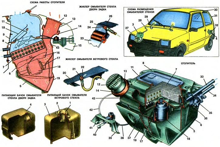
1. Filler cap. 2. Filter. 3. Windshield washer feed tank. 4. Tailgate window washer feed tank. 5. Air distribution cover. 6. Fan shroud. 7. Radiator. 8. Radiator shroud. 9. Rubber valve. 10. Water deflector. 11. Air intake cover. 12. Rotating deflector. 13. Deflector pipe. 14. Air duct seal. 15. Instrument panel. 16. Fan impeller. 17. Electric motor mounting spring clip. 18. Electric motor. 19. Protective cover. 20. Bonnet. 21. Windshield washer nozzle housing. 22. Windshield washer nozzle. 23. Tailgate glass. 24. Tailgate glass washer nozzle. 25. Tailgate glass washer nozzle housing. 26. Tailgate. 27. Windshield washer pressure pump. 28. Fluid supply pipe from the pump. 29. Windshield washer nozzle. 30. Tailgate glass washer nozzle. 31. Fluid supply pipe from the pump. 32. Tailgate glass washer pressure pump. 33. Outlet pipe. 34. Inlet pipe. 35. Heater tap. 36. Fan shroud mounting bracket. 37. Resistor. 36. Flexible tap rod. 39. Control lever bracket. 40. Heater valve control handle. 41. Air intake cover control handle. 42. Air intake cover flexible rod. 43. Guide casing.
Heating and ventilation of the passenger compartment
Ventilation, heating of the passenger compartment and blowing of the windshield are carried out by air sucked in from outside. Heating of the passenger compartment is provided by air heated in the radiator 7 of the heater, which is included in the engine cooling system parallel to the main radiator.
Outside air enters through the openings in the windshield frame (on the heater diagram it is shown with blue arrows) into the air intake box located in the rear part of the front end of the body. The air intake box is sealed against the ingress of smoky air from the engine compartment by a rubber seal pressed against the inner panel of the hood. In the air intake box, the water-deflecting shield 10 abruptly changes the direction of air movement, as a result of which rainwater separates and flows to the bottom of the box, from where it enters the engine compartment through an elastic rubber valve 9, preventing air from being sucked in from the engine compartment.
Air enters through the hatch, closed by the air intake cover 11. under the heater radiator casing 8. The air intake cover regulates the amount of air entering the passenger compartment through the radiator 7. The heater is attached to the shield reinforcement under the air intake box with four studs by the plastic radiator casing, which can be accessed under the instrument panel. The radiator casing 8 is sealed at the junction with the air intake box with a rubber sealing gasket. The heater radiator 7 is installed in the casing 8 and sealed along the perimeter with a rubber gasket.
Radiator 7 consists of two rows of tubes, cooling plates and two plastic tanks. The tubes and cooling plates are made of aluminum. To increase the heat transfer of the radiator, polypropylene turbulators are inserted into the tubes, turbulating the movement of the liquid in the tubes. The right tank of the radiator is divided by a partition into two cavities. The outlet pipe 33 and tap 35 with the inlet pipe 34 are bolted to the tank. The ends of pipes 33 and 34 exit into the engine compartment through the front shield and are connected by hoses to the engine cooling system. The outlet of the pipes into the engine compartment is sealed with a rubber seal (see picture top left), which is attached to the front shield with two screws.
Air from radiator 7 enters guide casing 43 and fan casing 6. The guide casing is installed between the radiator and fan casings, fastening is carried out by spring clamps to the radiator casing and additionally by two brackets 36.
In the center of the plastic guide casing, an electric motor 18 with a fan impeller 16 is mounted on two elastic pads by means of spring brackets 17. An additional electrical resistance (resistor) 37 is attached to the inner wall of the casing, which is connected and disconnected in the electric motor circuit by a three-position switch on the instrument panel and provides a low and high speed of rotation of the fan impeller.
From the fan casing, air rises through the window of the guide casing 43 into the air duct and then through pipes 13 and rotary deflectors 12 is supplied to the windshield or directly into the passenger compartment. The pipes of the deflectors with the air duct are sealed with rubber seals 14.
At the bottom of the fan casing, an air distribution cover 5 is hinged on brackets; when opened, air is directed to the feet of the driver and passengers. At the same time, the amount of air supplied to the deflectors is reduced.
The heater is controlled by the electric fan switch, rotary deflectors and two handles 40 and 41 for controlling the valve and the air intake cover. The lower handle for controlling the heater valve is connected by a flexible rod 38 to the valve lever 35 and regulates the amount of coolant coming from the cooling system to the heater radiator. The upper handle is connected by a flexible rod 42 to the air intake cover lever and regulates the amount of outside air coming into the heater.
To make it easier to remember the position of the control handles on the instrument panel on the left there are symbols in the form of triangles, the tops of which indicate that the air intake cover and valve are closed.
Many parts and components of the heater are interchangeable with parts of cars VAZ-2101, VAZ-2105 and VAZ-2106. Interchangeable with parts of the VAZ-2101 car: radiator casing with air intake cover, fan casing with air distribution cover, tap with inlet and outlet pipes, electric fan assembled with fastening parts and control levers with bracket assembled with parts of the VAZ-2105 - heater radiator assembled, resistor; with VAZ-2106 parts - deflector assembly with pipes.
Ventilation of the passenger compartment is carried out through the door windows. Additional inflow of outside air can be provided by opening the air intake cover (with the handle pulled to the right 41) and lowering the air distribution cover 5 The rotary deflectors can direct the air flow to the passengers. At low vehicle speeds, the amount of fresh air can be increased by turning on one of the fan speeds. To prevent the windshield from fogging up in autumn or spring, cold air is directed to the windshield by moving the upper handle 41 to the right, closing the air distribution cover 5 and moving the deflectors 12 so that the air stream is distributed over as large an area of the glass as possible.
To heat the incoming air, move the lower handle 40 to the right, thereby regulating the flow of liquid into the heater radiator.
To prevent the windshield from freezing in cold weather, the heater valve and air intake cover are opened with the handles. The direction of warm air is regulated with the deflectors. To supply warm air to the lower part of the passenger compartment, the air distribution cover 5 is opened.
In very cold weather, the air temperature in the passenger compartment can be increased by switching on one of the electric fan speeds and setting the air intake cover 11 to the partially open position. In these conditions, it is recommended to slightly open the door windows to prevent stagnation of cold air and accelerate its heating throughout the passenger compartment.
If you need to quickly warm up the windshield, close the air distribution cover and move the valve control handle all the way to the right. Warm air is directed only to the windshield by the rotating deflectors.
At an ambient temperature of -25°C, the fully switched on heater provides an average temperature in the passenger compartment of +25°C.
It is prohibited to turn on the electric fan when the air intake cover is closed and the heater valve is open.
Windshield washer
The washer together with the wiper ensures cleaning of the windshield in any operating conditions of the car without stopping it. The jet of washer fluid from the nozzles 29 wets the windshield and facilitates the movement of the wiper blade when cleaning the glass from dirt and dust.
The washer consists of a supply tank 3 for liquid, a pressure pump 27 with an electric motor, tubes and jets 29 that supply liquid to the glass. The supply tank must be large enough to ensure multiple use of the washer. The car has a polyethylene tank from a VAZ-21081 with a capacity of 2 liters, mounted on the bracket of the mudguard of the right wing of the body. The tank has a filler neck closed by a cover 1. Filter 2 is inserted into the neck.
The design of pump 27 with an electric motor is shown on sheet 36. From the pump, liquid is supplied to jets 29, which are interchangeable with jets of the VAZ-2108 automobile. The jets are installed in the openings of the outer panel of the hood. The sprayers of the jets with a spherical surface are inserted into the sockets of the plastic housings 21. The stream of liquid is injected through a calibrated opening of the sprayer into the upper zone of the sector described by the brush. The direction of the washing stream is adjusted by turning the sprayer in the desired direction using a needle inserted into the opening of the sprayer.
The washer uses a mixture of a special liquid "Autocleaner-2 glass" (30 cm³ per 1 l of water). In summer, it is permissible to use only clean water without liquid.
Rear door glass washer
The rear door glass washer consists of a supply tank 4, a pressure pump 32 with an electric motor, tubes and a nozzle 30.
Polyethylene tank 4 with a capacity of 2 l and jet 30 are interchangeable with the corresponding units of the VAZ-2104 car. The tank has a filler neck closed by a lid, is attached in the luggage compartment with two bolts using a clamp to the left inner panel of the side. Pump 32 with an electric motor is interchangeable with pump 27 (device see chapter 36). Tube 31 from the pump passes along the rear pillar of the body and through the hole in the upper part of the tailgate approaches the jet 30. The design of the jet differs from the jet 29 only in its dimensions and the shape of the body 25.