
In crankcase 6 (pic. 113) the steering mechanism is mounted on two bearings 14 and 27, a helical gear 15, which is engaged with the rack 20. The cylindrical part of the rack rests on the plastic sleeve 9, and the gear part is located between the gear 15 and the stop 16 of the rack. The spring-loaded stop of the rack provides rectilinear movement of the rack along the axis of the steering mechanism, its fixation in the lateral direction and the clamping of the rack to the gear. Between the end face of the stop and the nut 18, a minimum gap of 0.12 mm is laid to compensate for the thermal expansion of the parts and to prevent jamming in the engagement.
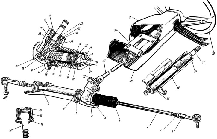
Pic. 113. Steering: 1 - outer tip of the steering rod: 2 - locknut; 3 inner tie rod end; 4 - protective cover; 5 - cross member of the subframe (steering gear support); 6 - steering gear housing; 7 — a collar of fastening of the steering mechanism; 8 - staples; 9 - rack bushing; 10 - support washer; 11 - ball pin insert; 12 - protective cap; 13 - ball joint pin; 14 - roller bearing; 15 - drive gear; 16 - rail stop; 17 - stop sealing ring; 18 - stop nut, 19 locking ring of the nut; 20 - rail; 21 lock nuts; 22 - ball bearing; 23 - seal; 24 - cover clamp, 25 - thrust stop; 26 - stop spring; 27 - ball bearing; 28 - retaining ring; 29 - protective washer; 30 - sealing ring; 31 - bearing fastening nut; 32 - boot: 33 - intermediate cardan shaft; 34 - steering column shaft mounting bracket; 35 - upper facing casing; 36 — steering wheel; 37 - steering column shaft; 38 — steering column shaft bearings; 39 — pipe steering column; 40 - lower facing casing; A, B - marks on the crankcase of the steering mechanism and on the anther.
At the threaded ends of the rail, internal hinges of the rod ends are installed. The inner hinge of the tip consists of a ball bearing 22 and a lock nut 21 screwed onto the threaded end of the rail, as well as a thrust stop 25 with a spring and a ball head of the inner tip 3 of the rod. The ball head is clamped between the spherical surface of the ball joint and the hemisphere of the ceramic-metal thrust stop using spring 26. The ball joint 22 is screwed onto the rail and fixed with a lock nut 21, which is locked both on the support and on the rail by pressing the belts into the grooves of the rail and support. The output of the rods from the crankcase of the steering mechanism is sealed with two protective covers 4. External tips 1 are screwed on the threaded sections of the rods of the inner tips, fixed with lock nuts 2. A spring-loaded insert 11 is located in the cavity of the outer tip, which compresses the ball head of the pin 13. This hinge is protected by a rubber cap 12.
The steering column shaft is composite, consists of the upper 37 and intermediate 33 cardan shafts. The upper shaft is tubular, mounted in the tube of the bracket 34 on two ball bearings 38. At its upper end, a steering wheel 36 is mounted on conical splines, and at the lower end there is a universal joint yoke of the intermediate shaft.