




- before attaching the traction joint and gear selection lever to the rod, degrease the threaded holes in the joint housing and the lever hub, as well as the mounting screws; apply TB-1324 sealant to the screw threads and tighten them;
- while doing this, make sure not to mix up the mounting screws. They have different lengths, coatings and tightening torques. The lever mounting screw is phosphated (dark color), its length is 19.5 mm, tightening torque is 2.4 kgf·m, and the hinge mounting screw is cadmium plated (golden color), its length is 24 mm, tightening torque is 1.9 kgf·m;
- before installing the primary shaft seal and the clutch release fork shaft, lubricate the working surface of the seal with a thin layer of Litol-24 grease and the clutch release fork shaft bushings with SHRUS-4 grease;
- put LSC-15 grease into the ball joint of the gear shift lever;
- fasteners are tightened to the torques specified in Appendix 1;
- the selection of differential bearing adjusting rings is carried out according to the rules specified below (see "Selecting the differential bearing adjusting ring");
- the secondary shaft is assembled in the reverse order of disassembly; in this case, the synchronizers are installed on the shaft in an assembled state using the A.70152* mandrel, having previously heated them to a temperature of 100°C.
- when the heated parts cool down, the blocking rings on the gear cones may seize. To prevent this, before installing the heated synchronizer on the shaft, a special fork-shaped gasket is installed between the blocking rings and the ends of the gears, which is removed after the parts have cooled down;
- when assembling the synchronizer, the locking rings are installed so that the protrusions A are located opposite the hub sockets for the locking springs (figure 73) lower height, not higher, otherwise the gears will not shift after assembly;
- to facilitate the installation of the retainer, apply a little consistent grease to its ball, insert it into the cracker and, pressing the spring with a screwdriver towards its socket, install the cracker in place assembled with the ball. In this case, the socket in the sliding coupling should be located opposite the ball (greatest depth).
* Cylindrical mandrel with an internal diameter of 35.2 mm; length 176 mm.
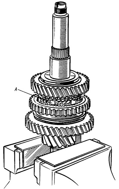
Figure 73. Assembly of the synchronizer of the 1st and 2nd gears
The differential assembly is carried out in the reverse order of disassembly, having previously lubricated the axle gears and satellites with engine oil. The axial clearance of the axle gear should be no more than 0.3 mm, and the moment of resistance to rotation of the differential gears should not exceed 1.5 kgf·m. If the clearance is increased, which is a sign of wear of the differential parts, replace the worn parts with new ones.
Using mandrel 67.7853.9565**, press the inner bearing rings onto the differential box, having first installed the speedometer drive pinion.
Having installed the clutch housing on the gearbox assembly stand, using the 67.7853.9563*** mandrel, press the rod seal into the socket, then insert the gear selection rod into the housing opening and secure the gear selection lever to it, having first degreased the threaded hole and screw and applied TB-1324 sealant to the screw thread.
Using mandrel 67.7853.9574****, the outer rings of the roller bearings of the primary and secondary shafts, complete with separators, are pressed into the clutch housing sockets, and the inner rings of these bearings are pressed onto the shafts.
** Cylindrical mandrel with an internal diameter of 35.5 mm and an external diameter of 45 mm.
*** Cylindrical mandrel with an internal diameter of 16.1 mm and an external diameter of 26 mm.
**** Cylindrical mandrel with guide belt diameter 25 mm and outer diameter 60 mm.
Install the gear selection mechanism, making sure that the gear selection rod lever is correctly positioned relative to the gear selection mechanism lever. Secure the gear selection mechanism. Then press the seal into the clutch housing, maintaining the size of (3.5±0.2) mm (see figure 61) so that the working edge of the seal is located on the polished belt of the shaft.
Press ball bearings onto the primary and secondary shafts, screw on the nuts and tighten them with a torque wrench, then caulk them. The length of the caulk should be 3.5-4 mm and should not go over the shaft thread. When tightening the nuts on the shafts, lock the primary shaft with device 41.7816.4070 (Splined bushing).
The differential unit is installed in the clutch housing. To prevent the axle gears from shifting from their seats during assembly, one of them is fixed on the clutch housing side with a special mandrel or plug used during transportation of the differential.
Install the primary and secondary shafts together with the gears. Then install the axle with the reverse gear, making sure that the reverse fork fits into the slot of the intermediate gear. Then install the gear shift rods and secure the forks to the rods (figure 74). A cleaned magnet and a gasket between the clutch and gearbox housings are installed in the crankcase socket.
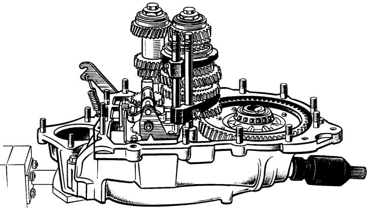
Figure 74. Installing the gear shift rods and forks
Select the adjusting ring for the differential bearings as shown below (see "Selecting the differential bearing adjusting ring"). Install the selected adjusting ring into the gearbox housing socket using the mandrel 67.7853.9575 (Cylindrical mandrel with an outer diameter of 72 mm and an inner diameter of 61 mm) press in the outer ring of the differential tapered roller bearing. Install the speedometer drive in place, then install the gearbox housing on the clutch housing and secure it with nuts. Install the mounting rings in the grooves of the primary and secondary shaft bearings. Install the rod and reverse fork retainers in place, secure the retainer cover and screw in the reverse fork retainer plug.