
Input shaft 17 (pic. 61) made in the form of a block of driving gears, which are in constant engagement with the driven gears of all forward gears. They are located on needle bearings on the secondary shaft 14. In addition to them, two synchronizers 12 and 10 are installed on the shaft. Together with the secondary shaft, the final drive gear is made. Double satellite differential. The preload in the differential bearings is adjusted by selecting the thickness of the ring 9. The driven gear of the final drive is attached to the flange of the differential box.
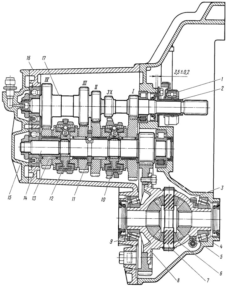
Pic. 61. Four-speed gearbox: 1 - clutch release bearing; 2 - guide sleeve of the clutch release bearing; 3 - drive gear of the speedometer drive; 4 - clutch housing; 5 - side gear; 6 - satellite; 7 - axis of the satellites; 8 - differential box; 9 - adjusting gasket; 10, 12 - synchronizers; 11 - persistent half rings; 13 - gear needle bearing; 14 - secondary shaft; 15 - rear cover of the gearbox housing; 16 gearbox housing; 17 - input shaft
Gearbox control drive 1 consists of lever 11 (pic. 62) with a spherical pin 12, a ball bearing 13, a rod 9 connected by a hinge 7 to a rod 6. and mechanisms for selecting and shifting gears. At the inner end of the rod 6, a lever 5 is fixed, which acts on a three-arm lever 3 of the gear selection mechanism 2. This mechanism is made as a separate unit and is attached to the clutch housing 4. The hole for the passage of thrust 9 is closed with a protective cover 10.
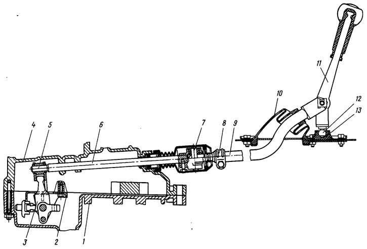
Pic. 62. Gearbox control drive (for clarity, the left part of the figure is rotated 90°around the axis of the thrust 6)
In building 16 (pic. 63) two axles are installed in the gear selection mechanism. One of them has a three-arm gear selection lever 3 and locking brackets 2. The other axis passes through the holes of the brackets 2, fixing them from turning. Shoulder B of lever 3 is used to engage forward gears, shoulder B is used to engage reverse gear, and lever 5 acts on the third shoulder (see fig. 62) gear selector. Under the action of a spring lever 3 (see fig. 63) gear selection and locking brackets 2 move on their axes until the ball 18 stops against the step on the axis 17. In this position, the brackets lock the reverse fork 12 with one end, entering its groove between the protrusions A, and with the other the fork of I and II gears (as well as the V gear fork in a five-speed gearbox); shoulder B of the gear selection lever is set to the position of switching on the III and IV gears. With the transverse movement of the gear lever towards the reverse direction, the lever 3 and brackets 2 move on the axles, compressing the spring. In this case, instead of the bracket, the shoulder B of the gear selection lever enters the groove of the reverse fork 12, and the brackets lock the forward gear forks. Thus, when lever 3 is moved along its axis, gears are selected, and when turning on the axis, gears are switched on.
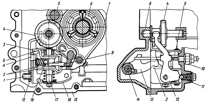
Pic. 63. Gear selection mechanism: 1 - fork axle; 2 - locking brackets; 3 - three-arm gear selection lever; 4 - intermediate reverse gear; 5 - input shaft; 6 - synchronizer of I and II gears; 7 - fork of inclusion of I and II transfers; 8 - axis of the intermediate reverse gear; 9 - guide axis of the locking brackets; 10 - reversing light switch; 11 - lock of the reverse fork; 12 - reverse fork; 13 - gear selection rod lever; 14 - gear selection rod; 15 - clutch housing; 16 - housing of the gear selection mechanism; 17 - axis of the gear selection lever; 18 - gear selector lever lock
In a five-speed gearbox, primary 7 (pic. 64) and secondary 4 shafts at the outlet of the crankcase 1 are extended. On this part of the shafts, the driving 8 and driven 2 gears of the V gear and its synchronizer 3 are located. The shaft bearings are fixed in their sockets by a plate 9. The gears of the V gear are closed by the rear cover 5 of the gearbox housing with breather 6.
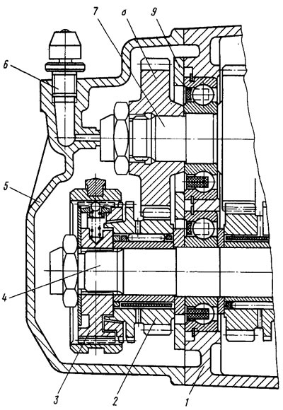
Pic. 64. Rear of a five-speed gearbox
To distinguish gearboxes by gear ratios of the main gear, they are marked with paint. The marking is applied on the top of the crankcase: 01 - for a gear ratio of 3.94; 02 - for a gear ratio of 4.13.
Possible malfunctions of the gearbox, their causes and methods of elimination are given in tab. 7.