




- disconnect the wires from the battery, from the starter traction relay and from the top dead center sensor;
- disconnect the speedometer drive cable from the speedometer drive housing by unscrewing the union nut;
- disconnect the ground wire from the clutch housing;
- unscrew the top dead center sensor from the clutch housing;
- disconnect the cable from the clutch release fork by unscrewing nuts 5 (see figure 57) from the lower end of the cable;
- unscrew the two upper bolts securing the clutch housing to the engine block and the upper nut securing the starter, and secure the bracket for slinging the power unit to the left stud securing the engine exhaust manifold.
Install crossbar 67.7820.9514 on the gutters (figure 65) to support the engine and hook its hook onto the bracket mounted on the exhaust manifold stud. If there is no crossbar, hang the power unit with a hoist.
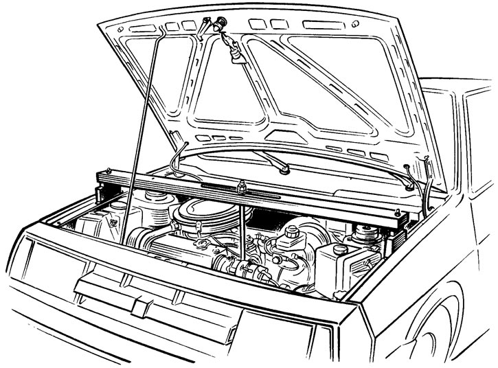
Figure 65. Installing crossmember 67.7820.9514 to support the power unit
The following operations are performed from underneath the vehicle:
- remove the engine splash guard and the lower clutch housing cover;
- drain oil from gearbox; disconnect the wires from the reverse light switch;
- loosen clamp 11 (figure 66) and disconnect the rod 10 from the gear selection rod hinge;
- unscrew the nut from the stud securing the upper part of the gearbox;
- disconnect the ball joints of the suspension arms from the steering knuckles;
- using puller 67.7801.9524 or by sharply striking the housing 12 of the inner joint with a hammer through a drift, knock out the joints from the axle gears and move the wheel drive shafts to the side. In case of difficulties in disconnecting the wheel drive from the axle gear on the vehicle, remove the gearbox assembly with the wheel drive and on the workbench, using the same puller, press out the joint from the axle gear;
- unscrew the three nuts on the left side from the studs that secure the gearbox to the left bracket 2 of the powertrain suspension, and then the nut from the bolt that secures the bracket itself. Having removed the bracket from the gearbox studs, take out the bracket 2 of the suspension from the eyes of the body side member;
- unscrew the bolts securing the rear support 9 of the powertrain suspension;
- unscrew the lower bolts securing the starter and remove it;
- install a special support with a hydraulic lift under the gearbox and, having slightly lowered the engine, unscrew the lower bolt securing the crankcase to the engine block and move the gearbox assembly with the clutch housing away from the engine to disconnect the gearbox shaft and the driven clutch disc;
- remove the gearbox. In this case, the primary shaft of the gearbox must not be supported on the petals of the clutch pressure spring, so as not to damage them.
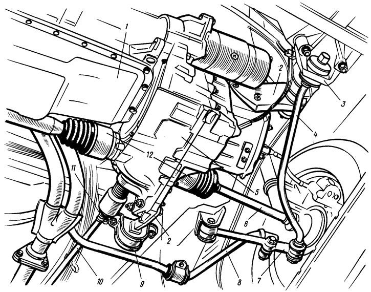
Figure 66. Fastening the gearbox to the vehicle: 1 - engine; 2 - powertrain suspension brackets; 3 - suspension arm tension bracket; 4 - stretching; 5 - gearbox; 6 - wheel drive shaft; 7 - suspension arm; 8 - anti-roll bar; 9 - rear engine support; 10 - gearbox control drive rod; 11 - clamp; 12 - inner hinge housings
(The original can be seen on the website: «www.vazbook.ru»)