




The suspension guide element is a beam consisting of two longitudinal levers 2 (figure 74) and connector 19, welded together through reinforcements. The lever connector is significantly offset forward from the wheel axis, it has a U-shaped section, which has high bending rigidity and low torsional rigidity. Due to the offset of the lever connector from the wheel axis and due to the specified section, the connector, twisting, works as a torsion, ensuring partial independence of the movement of each wheel.
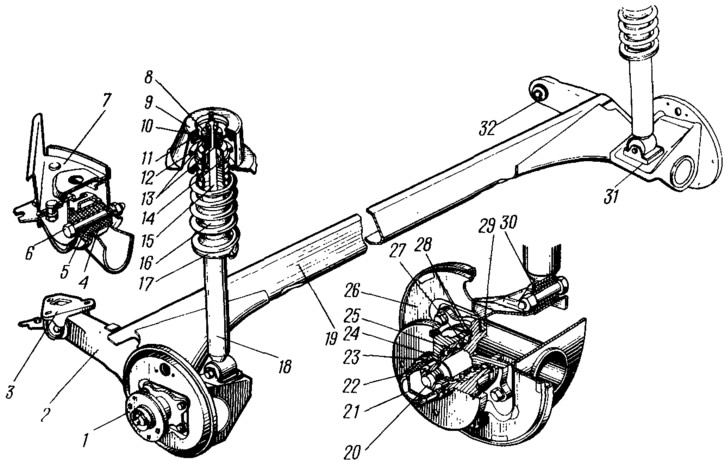
Figure 74. Rear suspension assembly:
1 - rear wheel hub; 2 - rear suspension arm; 3 - suspension arm mounting bracket; 4 - rubber bushing of the lever hinge; 5 - joint spacer sleeve; 6 - suspension arm mounting bolt; 7 - body bracket; 8 - shock absorber rod mounting support washer; 9 - Upper support of suspension spring; 10 - spacer spring; 11 - suspension spring insulating gasket; 12 - rear suspension spring; 13 - shock absorber rod mounting cushion; 14 - compression stroke buffer; 15 - shock absorber rod; 16 - shock absorber protective cover; 17 - lower support cup of suspension spring; 18 - shock absorber; 19 - lever connector; 20 - wheel hub axle; 21 - hub cap; 22 - wheel hub fastening nut; 23 - sealing ring; 24 - bearing washer; 25 - hub bearing; 26 - brake shield; 27 - retaining ring; 28 - mudguard; 29 - suspension arm flange; 30 - shock absorber bushing; 31 - lever bracket with eye for mounting shock absorber; 32 - rubber-metal hinge of the suspension arm.
Behind the linkage, a space is created that accommodates a spare wheel and a capacious gas tank. This is another advantage of the front-wheel drive layout and the adopted rear suspension design.
The longitudinal levers 2 are made of a pipe. Brackets 31 with lugs for fastening shock absorbers are welded to the rear part of the levers, as well as flanges 29, to which the axles 20 of the rear wheel hubs and shields 26 of the wheel brake mechanisms are bolted. At the front, each lever has a welded bushing, into which a rubber-metal hinge 32 is pressed, consisting of a rubber 4 and a metal 5 bushing. Bolt 6 passes through the spacer sleeve 5 of the hinge, connecting the lever of the suspension beam with a stamped bracket 3, which is fastened to the bracket 7 of the body with welded bolts with nuts and washers.
The spring 12 of the suspension is made of round spring steel. It is mounted on the shock absorber 18. Its lower part rests on the cup 17 welded to the shock absorber reservoir, and the upper part - through the insulating rubber gasket 11 - in the upper support 9, which is welded to the inner arch of the body.
The buffer 14 of the compression stroke is made of polyurethane. It is installed on the shock absorber rod inside the suspension spring. From above, the buffer rests against the cover of the protective casing 16, and when switched on, against the buffer support, which is put on the upper part of the shock absorber reservoir. The casing 16 protects the shock absorber rod 15 and the buffer of the compression stroke from mechanical damage and contamination.