

During the production of VAZ-2108 cars, minor changes were made to their electrical equipment circuitry aimed at improving the reliability of various systems and components. So, a starter relay was added, an ignition relay (see fig. 106), glove box lighting lamp. The fog light switch-on scheme in the rear lights has been changed (see chapter «Lighting and light signaling system»), backlighting of the outdoor lighting switch key has been added. There may be some minor changes to the scheme in the future.
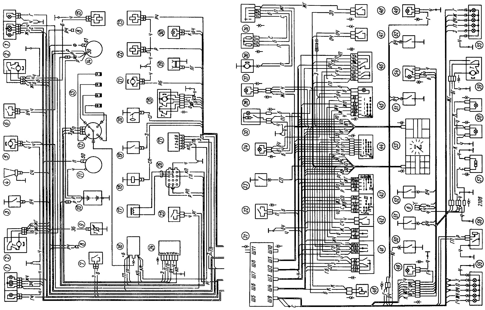
On cars, a single-wire circuit for switching on electrical equipment is used (pic. 91). WITH «a plus» consumers are connected to power sources by a wire, and with «minus» - through the car body or «mass». This method allows you to reduce the number of wires and simplify their installation. Ground connection «minus» power sources reduces the wear of metal body parts due to electrochemical corrosion.
Open large image in new tab »
Pic. 91. Scheme of electrical equipment of cars VAZ-2108 and VAZ-2109:
1 - block headlight; 2 - headlight cleaner motor *; 3 - engine compartment lamp switch; 4 - sound signal; 5 - electric motor of the fan of the engine cooling system; 6 - sensor for turning on the electric fan; 7 - reverse light switch; 8 - wire tip for connecting to the brake pad wear sensor *; 9 - temperature indicator sensor; 10 - battery; 11 starter; 12 sensor-distributor ignition; 13 - spark plugs; 14 - generator; 15 - solenoid valve for headlight washer *; 16 - ignition coil; 17 - top dead center sensor; 18 - solenoid valve of the carburetor; 19 - carburetor limit switch; 20 - oil pressure warning lamp sensor; 21 - washer motor; 22 - solenoid valve for turning on the windshield washer; 23 - solenoid valve for turning on the rear window washer *; 24 - switch; 25 - brake fluid level sensor; 26 - diagnostic block; 27 - control unit for the carburetor solenoid valve; 28 - windshield wiper motor; 29 - socket for a portable lamp; 30 - engine compartment lamp; 31 - mounting block; 32 - stoplight switch; 33 - switch for the carburetor air damper control lamp; 34 - panel for lighting the heater levers; 35 - cigarette lighter; 36 - glove box lighting lamp; 37 - heater motor; 38 - additional heater motor resistor; 39 - heater motor switch; 40 - instrument lighting switch; 41 - switch for direction indicators, headlights and parking light; 42 - horn switch; 43 - switch cleaner and average glass; 44 - ignition switch; 45 - outdoor lighting switch; 46 - alarm switch; 47 - fog light switch; 48 - rear window heating switch; 49 - side direction indicator; 50 - switch of the control lamp of the parking brake system; 51 - ceiling light switch in the front door pillar; 52 - ceiling light switch in the rear door pillar **; 53 - instrument cluster; 54 - ceiling; 55 - rear light; 56 - sensor for level indicator and fuel reserve; 57 - rear window heating element; 58 - license plate lights; 59 - rear window cleaner *; B - plug connector for connecting to the ceiling lamp for individual interior lighting.
* Installed on car parts.
** Installed on VAZ-2109 and VAZ-21093 vehicles.
1 - block headlight; 2 - headlight cleaner motor *; 3 - engine compartment lamp switch; 4 - sound signal; 5 - electric motor of the fan of the engine cooling system; 6 - sensor for turning on the electric fan; 7 - reverse light switch; 8 - wire tip for connecting to the brake pad wear sensor *; 9 - temperature indicator sensor; 10 - battery; 11 starter; 12 sensor-distributor ignition; 13 - spark plugs; 14 - generator; 15 - solenoid valve for headlight washer *; 16 - ignition coil; 17 - top dead center sensor; 18 - solenoid valve of the carburetor; 19 - carburetor limit switch; 20 - oil pressure warning lamp sensor; 21 - washer motor; 22 - solenoid valve for turning on the windshield washer; 23 - solenoid valve for turning on the rear window washer *; 24 - switch; 25 - brake fluid level sensor; 26 - diagnostic block; 27 - control unit for the carburetor solenoid valve; 28 - windshield wiper motor; 29 - socket for a portable lamp; 30 - engine compartment lamp; 31 - mounting block; 32 - stoplight switch; 33 - switch for the carburetor air damper control lamp; 34 - panel for lighting the heater levers; 35 - cigarette lighter; 36 - glove box lighting lamp; 37 - heater motor; 38 - additional heater motor resistor; 39 - heater motor switch; 40 - instrument lighting switch; 41 - switch for direction indicators, headlights and parking light; 42 - horn switch; 43 - switch cleaner and average glass; 44 - ignition switch; 45 - outdoor lighting switch; 46 - alarm switch; 47 - fog light switch; 48 - rear window heating switch; 49 - side direction indicator; 50 - switch of the control lamp of the parking brake system; 51 - ceiling light switch in the front door pillar; 52 - ceiling light switch in the rear door pillar **; 53 - instrument cluster; 54 - ceiling; 55 - rear light; 56 - sensor for level indicator and fuel reserve; 57 - rear window heating element; 58 - license plate lights; 59 - rear window cleaner *; B - plug connector for connecting to the ceiling lamp for individual interior lighting.
* Installed on car parts.
** Installed on VAZ-2109 and VAZ-21093 vehicles.
All diagrams in the section «electrical equipment», the color of the wires is indicated by letters, and the first letter is the color of the wire itself, and the second is the color of the strip on the wiring (if it exists). Basically, the first letter of the color name is taken: B - white, G - blue, F - yellow, 3 - green, K - brown, O - orange, R - pink, C - gray, F - purple, H - black. The exception is red, which is assigned the letter P (purple).
To facilitate installation, all wires are bundled, and most of the bundles are made flat. In these harnesses, wires are welded to a PVC plastic tape. Flat harnesses are more convenient to mount on a car, especially under body upholstery parts. In addition, in flat bundles, the conditions for cooling the wires are better and therefore wires with a smaller cross-section of the conductive core can be used. As a result, copper and plastic compound used for insulation are saved.
To connect the wires, small-sized flat plug-in lugs with an internal plug width of 2.8 mm are used. Plug-in sockets protect the connections well from water and dirt, which contributes to the reliable operation of electrical equipment systems, especially the ignition system.
The connecting node of the entire electrical wiring of the car is the mounting block (pic. 92), located in the air box on the left side of the vehicle. Through it, the front wiring harnesses are connected to the instrument panel wiring harness and to the rear wiring harness. The colors of the wires connected to the plugs of the mounting block, and the conditional numbering of the plugs in the blocks are given in fig. 93 and 94. For ease of maintenance, all fuses and auxiliary relays are placed in the mounting block, including headlights, windshield wipers and washer, rear window heating, etc.
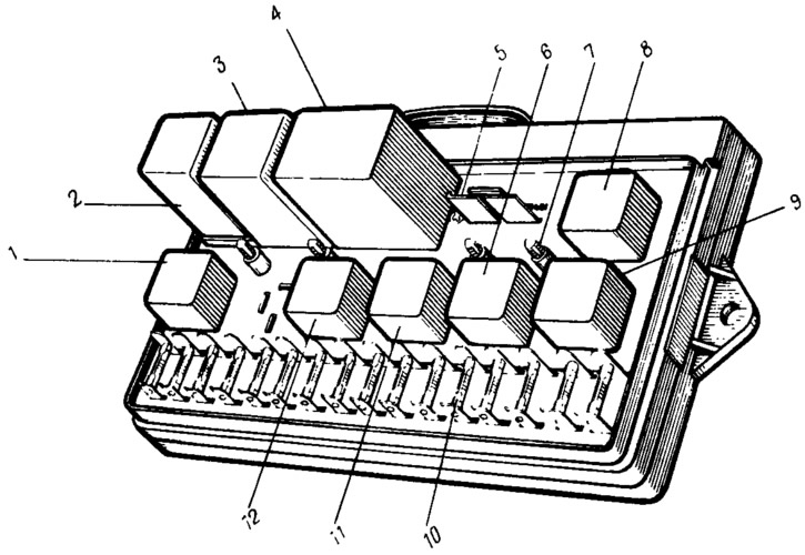
Pic. 92. Mounting block (cover removed):
1 - relay for switching on headlight cleaners (K6); 2 - rear window washer time relay (K1); 3 - relay-interrupter of direction indicators and alarm (K2); 4 - wiper relay (K3); 5 - contact jumpers in place of the lamp health monitoring relay; 6 - relay for turning on the heated rear window (K10); 7 - spare fuse; 8 - high beam headlight relay (K5); 9 - relay for switching on the dipped headlights (KP); 10 - fuse; 11 - relay for turning on the electric motor of the fan of the engine cooling system (K9); 12 - relay for turning on the sound signal (K8).
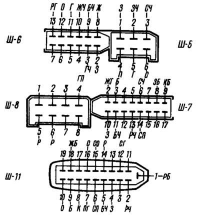
Pic. 93. Colors of wires connected to the mounting block in the engine compartment (the numbers indicate the conditional numbers of the plugs):
Ш5 and Ш6 - pads connected to the front wiring harness; Ш7 and Ш8 - pads connected to the wiring harness of the left mudguard; Ш11 - a block connected to the wiring harness of the air intake box.
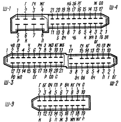
Pic. 94. Colors of wires connected to the mounting block in the car (the numbers indicate the conditional numbers of the plugs):
Ш9 - a block connected to the rear wiring harness; Ш1—Ш4 - pads connected to the instrument panel wiring harness.
Electrical connections inside the mounting block (pic. 95) made on two double-sided printed circuit boards connected by soldering into a single unit. All output plugs of the mounting block are also riveted to the printed circuit boards. In order not to accidentally burn out the conductive tracks of printed circuit boards, it is not allowed to short the wires to ground when checking the health of the electrical circuit.
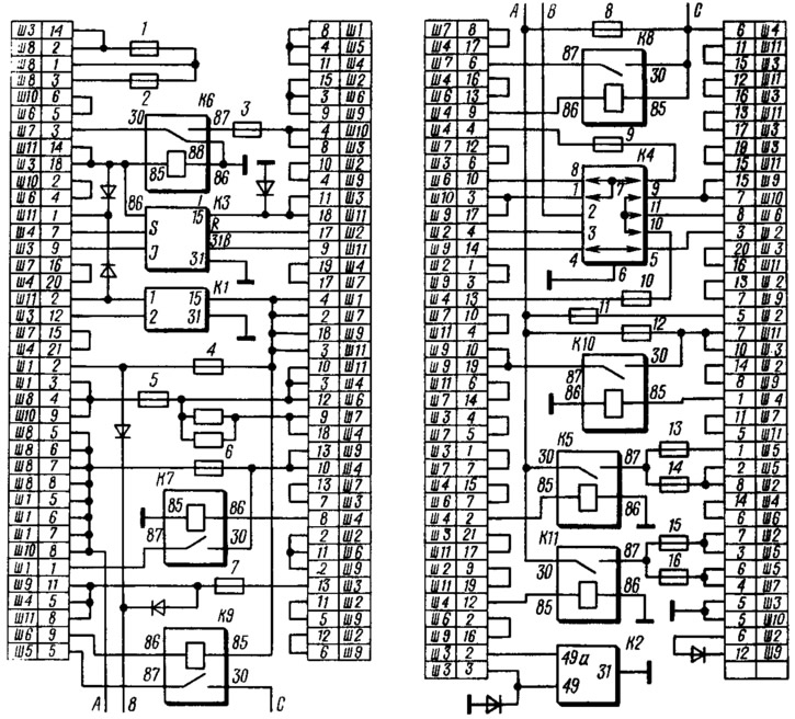
Pic. 95. Connection diagram of the mounting block (the outer number in the designation of the wire tip is the number of the block, and the inner number is the conditional number of the plug):
K1 - rear window washer time relay; K2 - relay-breaker for direction indicators and alarm; K3 - wiper relay: K4 - lamp health monitoring relay (inside shows the contact jumpers that are installed instead of the relay); K5 - high beam headlight relay; K6 - relay for switching on headlight cleaners; K7 - power window relay (not installed on VAZ-2108 and VAZ-2109); K8 - relay for turning on the sound signal; K9 - relay for turning on the electric motor of the fan of the cooling system; K10 - relay for turning on the heating of the rear window; K11 - relay for switching on the dipped headlights.
From above, the mounting block is closed with a transparent plastic cover, on which a symbol is applied against each fuse and relay (symbol), showing which units of electrical equipment this fuse protects or turns on one or another relay. In total, there are 16 fuses in the mounting block. 13 of them are rated at 8 A, and three are rated at 16 A. These fuses protect most of the vehicle's electrical power circuits (see table. 3). The geared motors of the windshield, headlight and rear window cleaners also have additional thermal bimetallic fuses to protect against overloads.
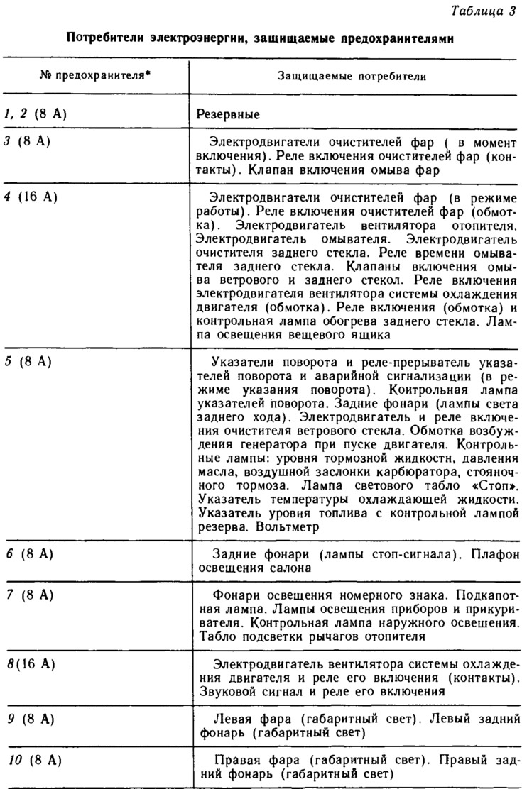
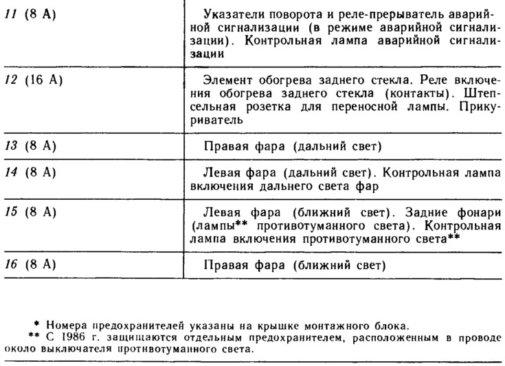
The engine ignition system is not protected by a fuse so as not to introduce an extra element into it, which reduces the reliability of the system in operation. The motor start circuit is also not protected so as not to reduce the reliability of the start. In addition, the battery charging circuit, the carburetor solenoid valve control circuit, and the dipped and high beam relays are not protected by fuses.
The supply voltage to most consumers is supplied through the ignition switch. The power circuits of those electrical equipment components, the operation of which may be required under any circumstances, are always connected to the battery (regardless of the position of the key in the ignition switch). These components include: horn, brake lights in the rear lights, cigarette lighter, interior light, socket for a portable lamp and an alarm power circuit.