

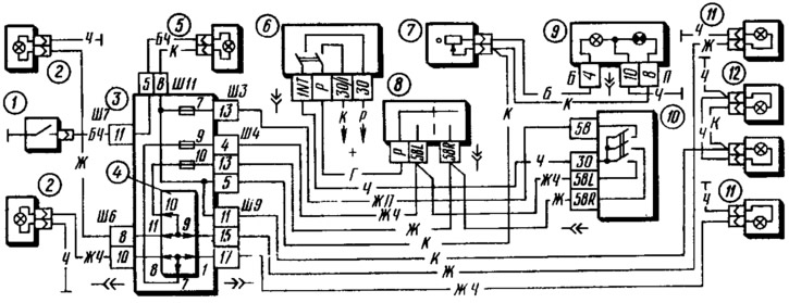
Pic. 123. Scheme for switching on outdoor lighting:
1 - engine compartment lamp switch; 2 - side light lamps in block headlights; 3 - mounting block; 4 - contact jumpers at the installation site of the lamp control relay; 5 - engine compartment lamp; 6 - ignition switch; 7 - instrument lighting switch; 8 - parking light switch; 9 - instrument cluster with instrument lighting lamps (left) and a control lamp for outdoor lighting (on right); 10 - outdoor lighting switch; 11 - side light lamps in the rear lights; 12 - license plate lights.
To enhance the side light of the rear lights in conditions of poor visibility (like in the fog) in the rear lights there are additional fog light bulbs 10 (see fig. 122), which are switched on by the fog light switch 6. The corresponding indicator lamp in the instrument cluster also lights up.
In the rear lights, in addition to the position and fog light bulbs, there are also reversing light, brake light and direction indicators. The reversing light is turned on by a switch located on the gearbox when reverse gear is engaged, if the ignition switch is in the position «I» («Ignition»), The brake lamps are turned on by a switch located on the clutch and brake pedal bracket when the brake pedal is depressed.
The cars also have a parking light. It can be switched on with the left stalk lever 8 (see fig. 123), if the key in the ignition switch is in position «III» («Parking»), In this case, instead of direction indicators (that would turn on on a moving car) the lamps of the side light of the left or right side of the car are switched on.
Direction indicators. Lamps I (pic. 124) direction indicators in the headlights, lamps 9 in the rear lights, as well as side direction indicators 2 are switched on by the left lever of the steering column switch 6 when the ignition is on. The intermittent lighting of the lamps is provided by an electronic relay-interrupter of direction indicators and alarms installed in the mounting block 3. The same relay turns on the indicator lamp in the instrument cluster 7 (left in the diagram) and check the serviceability of the direction indicator lamps. If any of the direction indicator lamps does not light up, the control lamp will flash at double the frequency.
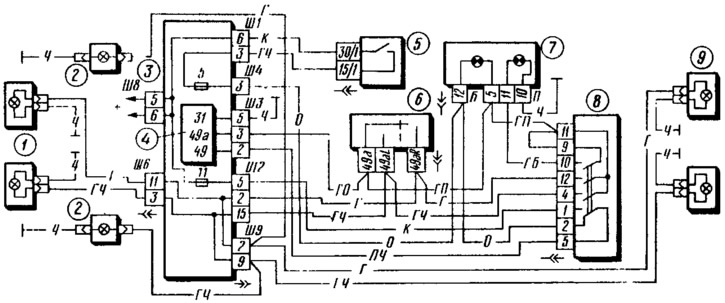
Pic. 124. The scheme of inclusion of direction indicators and alarms:
1 - direction indicator lamps in headlights; 2 - side direction indicators; 3 - mounting block; 4 - relay-breaker for direction indicators and alarms, 5 - ignition switch; 6 - turn signal switch; 7 - a combination of devices with control lamps of direction indicators (left) and alarm (on right); 8 - alarm switch; 9 - turn signal lamps in the rear lights.
The alarm is switched on by switch 8. At the same time, all direction indicator lamps are lit simultaneously with intermittent light. The flashing of the lamps is also provided by a relay-breaker 4. To control the operation of the alarm, a control lamp in the instrument cluster 7 is used (first on the chart).
The alarm can be turned on at any position of the key in the ignition switch, since the voltage for the operation of the alarm, bypassing the ignition switch, is supplied directly from the power sources through fuse 11.