
On the part of the VAZ-21083 and VAZ-21093 cars, a microprocessor (digital) ignition system. The basis of this system is the controller, which is a specialized microcomputer. According to the signals from the sensors, the controller, according to a given program, accurately determines the moment of ignition in the engine cylinders and issues commands to the switch. As a result, fuel consumption is reduced, exhaust emissions are reduced and optimal engine performance is achieved. The microprocessor ignition system includes the following original components: a controller, a two-channel switch, two ignition coils and sensors for reference, angular impulses and temperature. The switch, spark plugs and high voltage wires are the same as in the non-contact ignition system.
Ignition switch
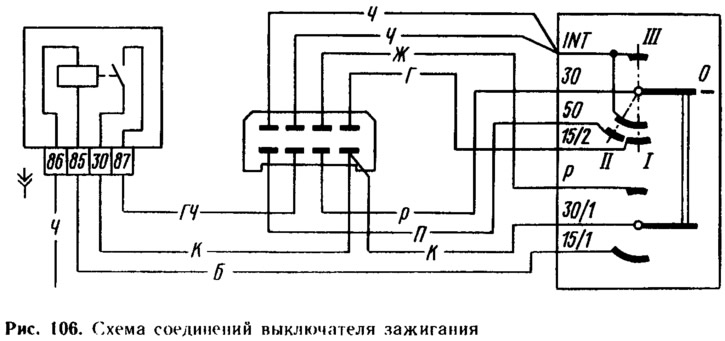
The ignition switch is designed to turn on and off the ignition and start circuits, control devices, lights and other consumers of the car's electricity. Ignition switches are installed in two types: KZ813, manufactured in VNR, or 2108-3704005-40 of domestic production. They are interchangeable, but have a different design. The ignition switch kit includes an additional ignition relay, which was not used on the first batches of VAZ-2108 cars. The connection diagram of the ignition switch with an additional relay is shown in fig. 106.
The ignition switch consists of two main parts: contact and lock. The lock part has an anti-theft device and a blocking device against restarting the starter. The principle of operation of the anti-theft device is that after removing the key from the lock in position III («Parking») the locking rod of the lock extends, enters the groove of the steering shaft and locks the shaft. The lock is designed so that the key can only be removed in position III.
The locking device against restarting the starter does not allow the key to be turned again from position I («Ignition») to position II («Starter»), The starter can only be reactivated after the key has been returned to the «ABOUT» («Turned off»). Thanks to this device, the starter is protected from accidental activation while the engine is running, which can lead to damage to the starter drive.
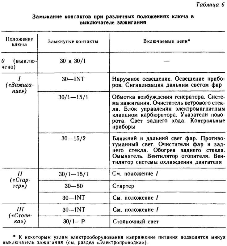
The contact part of the ignition switch is non-separable. Voltage from the battery and generator is supplied to the contacts «30» and «30/1». In table. 6 shows which switch contacts close at different key positions.
Spark plug
Spark plugs are used to ignite the working mixture in the cylinders by a spark discharge between the electrodes. The vehicles in question are fitted with FE65P spark plugs (made in SFRY) or candles of type A-17DV-10 of domestic production. The letter A in the designation of the candle indicates the thread length of the screwed part M14X 1.25. The numbers 17 characterize the glow number of the candle. The second letter D in the designation indicates that the length of the threaded part of the candle body is 19 mm. The last letter B means that the thermal cone (skirt) insulator protrudes beyond the end of the housing.
Candles A-17DV-10 differ from candles A-17DV (used on cars «Zhiguli») the shape of the insulator, the increased thickness of the side electrode and the introduction of an anti-corrosion coating on the body. All this increases the reliability of the candle at higher voltages and increases its durability.
Since 1988, FE65PR or FE65CPR spark plugs can be installed on the vehicles in question, which have a 4... 10 kOhm interference suppression resistor inside. With these candles, high voltage wires without interference suppression tips are placed on the engine.
Ignition coil
Ignition coil converts low voltage intermittent current (12 V) into high voltage current (20...25 kV), necessary for the breakdown of the air gap between the electrodes of the spark plugs. Ignition coil type - 27.3705. It is a transformer with an open magnetic circuit, which consists of an inner core and an outer ring magnetic circuit. The secondary winding, which has a large number of turns, is wound around the core. One end is connected to the center terminal of the ignition coil, and the other end is connected to the low voltage terminal «B». Primary winding (with fewer turns) wound over the secondary. Its conclusions are connected to low-voltage terminals. To increase the reliability of insulation and improve cooling, the ignition coil is filled with transformer oil.
On cars with a digital ignition system, two ignition coils of type 29.3705 are installed, molded in plastic, each with two high-voltage terminals. One ignition coil generates high voltage pulses for the spark plugs of the 1st and 4th cylinders, and the other for the spark plugs of the 2nd and 3rd cylinders.
Ignition distributor
The ignition distributor sends low voltage control pulses and distributes high voltage pulses to the spark plugs. Distributor sensor type - 40.3706. It is four-spark, with vacuum and centrifugal ignition timing controls.
Building 13 (pic. 107) cast from aluminum alloy. Roller 15 rotates in two porous ceramic-metal bushings impregnated with oil. Sleeve 17 is pressed into the body, and sleeve 25 is in holder 7. The main parts of the ignition distributor sensor: sensor, centrifugal ignition timing controller, vacuum ignition timing controller and ignition distributor.
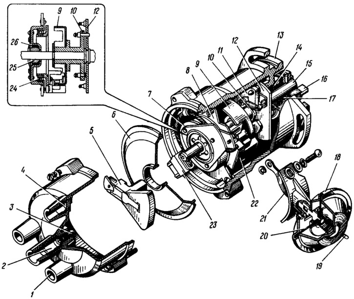
Pic. 107. Sensor-distributor ignition:
1 - cover; 2 - terminal for the wire from the ignition coil; 3 - central carbon electrode; 4 - side electrode with terminal; 5 - rotor; 6 - protective screen; 7 - holder of the front roller bearing; 8 - sensor support plate; 9 - screen; 10 - driven plate of the centrifugal regulator; 11 - weight; 12 - leading plate; 13 - ignition distributor sensor housing; 14 - stuffing box; 15 - roller; 16 - clutch; 17 - bushing of the rear end of the roller; 18 - housing of the vacuum regulator; 19 - fitting for vacuum supply; 20 - diaphragm; 21- thrust of the vacuum regulator; 22 - proximity sensor; 23 - plug connector; 24 - sensor support plate bearing; 25 - bushing of the front end of the roller; 26 - felt ring.
Sensor 22 - non-contact microelectronic, based on the use of the Hall effect. This effect consists in the appearance of a transverse electric field in a semiconductor plate with current under the action of a magnetic field on it. The sensor consists of a permanent magnet, a semiconductor plate and an integrated circuit. There is a gap between the plate and the magnet.
In the gap of the sensor there is a steel screen 9 with four slots. When a screen slit passes through the gap, a magnetic field acts on the semiconductor plate and the potential difference is removed from it. If the screen body is in the gap, then the magnetic lines of force close through the screen and do not act on the plate. In this case, there is no potential difference across the plate.
An integrated circuit built into the sensor converts the potential difference created on the plate into negative voltage pulses of a certain value at the output of the sensor (pic. 108,II). When the screen is in the gap of the sensor, then there is a voltage U at its outputmax about 3 V less than the supply voltage. If a screen slot passes through the sensor gap, then the voltage Umax at the output of the sensor is close to zero (no more than 0.4 V). The ratio of period T to duration TAnd momentum (duty cycle) equal to 3. Sensor supply voltage 8...14 V.
Centrifugal Ignition Advance Controller consists of a leading plate 12, mounted on a roller 15, a driven plate 10 and two weights 11. The weights rotate on axles riveted to the leading plate. A screen 9 is riveted to the sleeve of the driven plate. Thus, the driven plate 10 is integral with the screen 9 and can rotate within small limits on the roller 15.
Vacuum Ignition Advance Controller 18 is fixed on the housing of the sensor-distributor. A diaphragm 20 is clamped between the body and the cover of the regulator. On the one hand, a rod 21 is attached to the diaphragm, and on the other hand there is a spring. The rod is pivotally connected to plate 8, on which a proximity sensor is mounted. Under the action of rarefaction, the diaphragm bends and through the rod 21 turns the plate 8 against the direction of rotation of the roller 15.
Distributor consists of a rotor 5 mounted at the end of the roller 15 and electrodes 4 embedded in a plastic cover 1. The central and outer contacts are riveted and filled with epoxy resin to the plastic rotor 5, as well as a 1 kOhm resistor designed to suppress radio interference. A spring-loaded carbon electrode 3 rests against the central contact of the rotor, which transmits high voltage pulses from the ignition coil to the rotor. When the rotor rotates, these impulses are transmitted from the outer contact to the side electrodes 4 and then to the spark plugs.
Switch
The switch converts the control pulses of the sensor and current pulses in the primary winding of the ignition coil. On cars with a contactless ignition system, a single-channel electronic switch 36.3734, or 3620.3734, or 56.3734, or HIM-52 is used (produced by Hungary). All of them are interchangeable. The digital ignition system uses a two-channel switch type 42.3734.
During the passage of a positive impulse (voltage Umax, see fig. 108,II) from the non-contact sensor there is a gradual (within 4.8ms) increase in current strength in the primary winding of the ignition coil to a maximum value V (see fig. 108, I), equal to 8... 9 A. At the moment when the voltage at the output of the sensor drops to the output transistor of the switch, it closes and the current through the primary winding of the ignition coil is abruptly interrupted. As a result, a high voltage pulse is induced in the secondary winding.
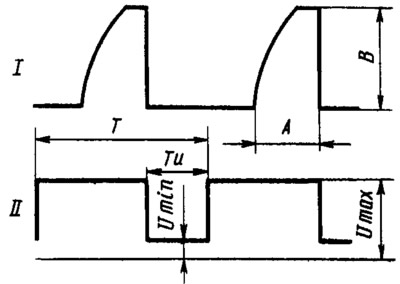
Pic. 108. Switch impulses (I) and proximity sensor (II) on the oscilloscope screen:
t - current accumulation time; B is the maximum current value; T - pulse period; TAnd - pulse duration.
High voltage wires
High voltage wires transmit high voltage pulses from the ignition coil to the distributor and from it to the spark plugs. To reduce radio interference, the wires have a resistance distributed along the length of 2000 Ohm / m for wires of the PVVP-8 type (Red) and 2500 Ohm/m for PVSh1V-40 wires (of blue color). From the side of the spark plugs, tips with noise suppression resistors with a resistance of 5.6 kOhm are placed on the wires. If FE65PR or FE65CPR spark plugs are used, noise suppression tips are not installed on the wires.
Controller
controller type «Electronics MS2713-02» serves to control the sparking moment in the digital ignition system, as well as to control the carburetor solenoid shut-off valve. It is an electronic microprocessor system and is essentially a miniature specialized computer. Its memory contains the values of the ignition timing, which must correspond to a given crankshaft speed, vacuum in the intake pipe and coolant temperature.
According to the signals from the sensors, the controller selects the required ignition timing from the memory and, at a strictly defined moment, issues ignition signals to the switch. In addition, depending on the carburetor throttle position and engine speed, the controller turns on or off the carburetor solenoid shut-off valve.
The controller has a built-in pressure sensor connected by a hose to the engine intake pipe. All controller outputs are made in the form «open collector» transistor structure npn with a load capacity of not more than 10 m.
Synchronization sensors
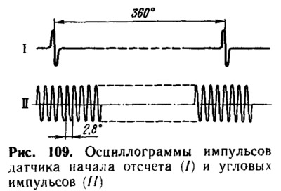
Synchronization sensors used in the digital ignition system, type 14.3847, are installed on the clutch housing. The sensors are designed to synchronize the operation of the controller with the V. M. T. pistons of 1 and 4 cylinders (reference switch or NO) and angular position of the crankshaft (encoder of angular impulses or IR). The YI sensor is located above the gear rim of the flywheel, and the NO sensor is located above a special marker pin pressed into the flywheel.
Both sensors are the same, made in the form of a coil with a magnetic core. The principle of operation of sensors is based on the law of electromagnetic induction. When a ferromagnetic object passes under the sensor core (e.g. flywheel ring tooth), an EMF is induced in the sensor coil. Its value depends on the gap between the sensor core and the crown tooth, as well as on the crankshaft speed.
The NO sensor generates one pulse per revolution of the crankshaft at the moment the marker pin passes through its magnetic field. This moment corresponds to the position of V.M.T. pistons 1 and 4 cylinders. The UI sensor creates impulses when the teeth of the flywheel rim pass in its magnetic field. Since the number of crown teeth is 128, then the pulse period of the sensor UI is 360/128=2.8°along the crankshaft.
The pulses generated by the NO and UI sensors are shown in fig. 109. The amplitude of the voltage pulses is from 0.2 to 100 V in the range of crankshaft speeds from 25 to 6000 rpm. The gap between the sensor core and the top of the flywheel crown tooth or the end of the marker pin should be 0.3...1.2 mm.
Coolant temperature sensor
Engine coolant temperature sensor used in the digital ignition system, type 19.3828, semiconductor, linear. It is installed on the outlet pipe of the engine cooling jacket. Inside the sensor housing is a special microcircuit. A constant current of 1.5 mA is applied to the sensor outputs. Depending on the temperature, the voltage drop across the sensor outputs changes (microchips). This voltage drop when the sensor is supplied with a constant current of 1.5 mA is numerically equal to (in millivolts) coolant temperature in K multiplied by ten.
The output voltage of the sensor in the controller is converted into two types of signals. A temperature below 50°C corresponds to a low level signal, and a temperature above 50°C corresponds to a high level signal. These signals select the ignition timing for two engine states: cold or hot.