
The dipped and main beam headlights are switched on by the left lever of the steering column switch 9 (pic. 122), if the key of the switch 8 of external lighting is fully pressed. The headlights are not turned on directly from the switch, but through auxiliary relays 3 and 4 installed in the mounting block 2. This is done in order to reduce the current flowing through the switch contacts.
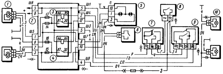
Pic. 122. Scheme of inclusion of headlights and fog light:
1 - block headlights: 2 - mounting block; 3 - relay for switching on high beam headlights; 4 - relay for turning on the dipped headlights; 5 - instrument cluster with control lamps for high beam headlights (left) and fog light (on right): 6 - fog light switch in the rear lights; 7 - ignition switch; 8 - outdoor lighting switch; 9 - headlight switch; 10 - fog lamps in the rear lights.
Regardless of the position of the switch button 8, the high beam can be switched on briefly (i.e. carry out signaling with high beam headlights), by pulling the stalk switch lever towards you. This is ensured by the fact that the voltage on the contact «30» The light signaling of switch 9 is supplied directly from the ignition switch 7, bypassing switch 8.
Switching on the main beam in the headlights is controlled by a lamp installed in the instrument cluster 5 (left in the diagram).
The headlight reflector together with the diffuser form an optical element. The inner surface of the diffuser is made in the form of a complex system of prisms that scatter light in the horizontal direction. From the back, a lamp of the AKG 12-60 + 55 type is inserted into the optical element. The lamp is halogen, that is, its bulb is filled with iodine vapor and an inert gas. The light output and durability of such a lamp is almost twice as high as conventional ones.
The lamp has two tungsten filaments: one (55 W) for low beam and other (60 W) - for the far. The high beam thread is at the focus of the reflector, so the high beam beams are concentrated into a narrow beam, directed almost parallel to the road and well illuminating it at the maximum distance from the car. The dipped beam thread is brought forward from the focus of the reflector and is partially covered from below by a special metal screen. This is done to limit the upward propagation of light.
If you direct a beam of low beam at the wall, then the spot of light will have the shape of an ellipse with a cut off upper half. The upper boundary of the illuminated area in the left part of the spot will pass exactly along the horizontal axis of the ellipse, and in the right part - along a line extending upward from the center of the ellipse at an angle of 15°to its horizontal axis. This shape of the beam of light provides good illumination of the road in front of the car (especially her right side and curb) and reduces the possibility of dazzling oncoming drivers.
Some cars can be fitted with hydrocorrectors for headlights. They serve to adjust the headlight beam angle from the driver's seat depending on the load on the vehicle. The hydraulic corrector consists of a main cylinder mounted on the instrument panel, actuating cylinders on the headlights and connecting tubes. Cylinders and tubes are filled with a special fluid that does not freeze at low temperatures.
The hydraulic corrector handle located on the instrument panel changes the fluid pressure in the hydraulic corrector system. Under the influence of this pressure, the pistons of the actuating cylinders move and turn the optical elements of the headlights to the required position.
If there is no hydraulic corrector on the car, then plugs are placed on the headlights instead of the actuating cylinders.