




Open large image in new tab »
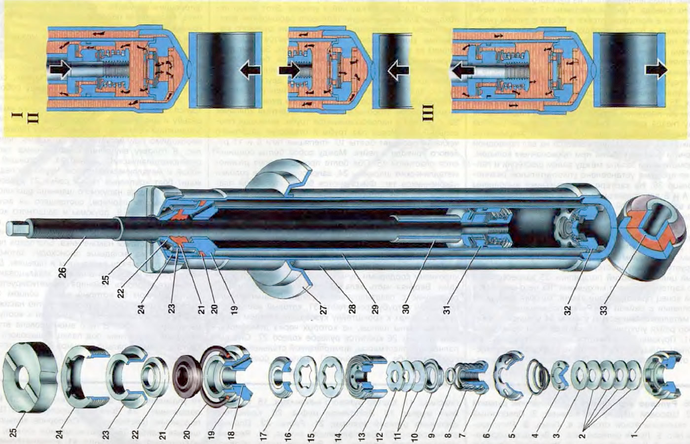
Figure 25. Rear suspension shock absorber: 1. Compression valve body; 2. Compression valve discs; 3. Compression valve throttle disc; 4. Compression valve plate; 5. Compression valve spring; 6. Compression valve cage; 7. Compression valve nut; 8. Recoil valve spring; 9. Recoil valve nut washer; 10. Recoil valve plate; 11. Recoil valve discs, 12. Recoil valve throttle disc; 13. Shock absorber piston; 14. Piston ring; 15. Bypass valve plate; 16. Bypass valve spring; 17. Restrictive plate of the bypass valve; 18. Rod guide bushing with fluoroplastic layer 19. Rod guide bushing collar, 20. Reservoir sealing ring; 21. Rod seal; 22 Protective ring of the rod; 23. Rod seal race; 24. Reservoir nut; 25. Compression buffer support; 26. Shock absorber rod; 27. Spring cup; 28. Shock absorber reservoir; 29. Shock absorber cylinder; 30. Spacer sleeve; 31. Piston assembly with recoil valve and bypass valve; 32. Compression valve assembly; 33. Shock absorber bushing assembly; I. Shock absorber operation diagram; II. Compression stroke; III. Recoil stroke.
The rear suspension shock absorber is hydraulic, telescopic, double-acting. It consists of a reservoir 28, a cylinder 29, a compression valve 32, a rod 26 assembled with a piston 31 and valves, a collar 19 with a guide sleeve 18 and sealing and fastening parts.
The reservoir 28 is made of a pipe, to the lower part of which a bottom with an eye is welded, and in the upper part an internal thread is cut for a nut 24. The lower support cup 27 of the suspension spring is welded to the outside of the reservoir.
Compression valve 32 is pressed onto the lower part of the cylinder and pressed by it to the bottom of the reservoir. It consists of housing 1, collar 6, plate 4, pack of disks 2 and 3 and spring 5. In the housing there is a central seat, to the chamfer of which the compression valve disks are pressed from above. In the upper and lower parts of the valve housing there are crosswise located cutouts for the passage of liquid. The pack of disks consists of four flat disks, one of which - the upper one - has two cutouts for throttling the liquid. The disks are pressed to the chamfer of the seat by spring 5 through plate 4, which has four through holes for the passage of liquid, and a cylindrical protrusion. With this protrusion the plate is pressed to the inner part of the throttle disk 3. Due to the cylindrical protrusion between the outer edges of the throttle disk and the plate, a gap is formed along the entire perimeter for the passage of liquid to the throttling cutouts of the disk. A sleeve 6 is pressed onto the valve body from above. It has a belt with a flange for fitting into the cylinder bore, one central and six peripheral holes for the passage of liquid.
In cylinder 29, rod 26 moves together with piston 31 and two valves: bypass and recoil. Guide sleeve 18 has a fluoroplastic layer on the inner surface, due to which the wear of the rod and sleeve is sharply reduced. Sleeve 19 of the guide sleeve is pressed into the cylinder. The sleeve has a channel for draining liquid from the annular cavity of the sleeve into the cavity of the reservoir, so that liquid pressure is not created on the gland 21. The sleeve of the guide sleeve is sealed in the reservoir with a rubber ring 20, which is pressed through the sleeve 23 of the gland with a nut 24 to the collar of the sleeve 19 and the surface of the reservoir. With the same nut, through the sleeve of the gland and the protective ring 22 of the rod, the gland 21 is pressed to the annular projection of the sleeve of the guide sleeve.
The seal 21 of the rod has three working edges, which are pressed against the chromed surface of the rod. The grooves under the lower working edges are made at an angle, due to which the liquid that has passed between the guide bushing and the rod creates pressure on the working edges of the seal, pressing them against the surfaces of the rod, which improves the seal. The support 25 of the compression buffer is put on top of the shock absorber reservoir.
The following are installed in the lower part of the rod: spacer sleeve 30, restrictive plate 17 of the bypass valve, spring 16 and plate 15 of the bypass valve, piston 13 with sealing ring 14, discs 11 and 12 of the recoil valve, thrust plate 10, spring 8 of the recoil valve and nut 7.
(Information copied from the portal VazBook.ru)
The distance sleeve 30 limits the movement of the rod during the recoil stroke, resting against the sleeve of the rod guide sleeve.
Piston 13 is metal-ceramic and has eight vertical channels located along circles of two radii. The channels located along circles of a larger radius are blocked from above by plate 15 of the bypass valve, which is pressed against them by flat spring 16. The remaining channels are blocked from below by a stack of discs of the recoil valve. Upper disc 12 is a throttle disc, it has four cutouts along the outer circumference: the next two discs 11 are flat. The stack of discs is pressed by spring 8 through support plate 10. The piston assembled with valves is fastened to the rod by nut 7, which is fixed by punching the end of the rod in two places. Between the nut and the lower disc of the recoil valve, washer 9 is installed, protecting the discs from damage when screwing or unscrewing the nut. Metal-ceramic ring 14 serves to create a seal.
Unlike the front suspension strut, the recoil stroke in the shock absorber is limited more rigidly - by the stop of the spacer sleeve 30 in the cage 19 of the rod guide sleeve.
In practice, the condition of the shock absorber can be checked as follows:
- place the car on a ramp or inspection ditch and swing it by the rear bumper, applying a force of 40...50 kgf. If the shock absorbers are in good condition, the number of free vibrations of the body should not exceed three;
- disconnect the lower attachment point of the shock absorber and pump it by hand. A serviceable shock absorber pumps smoothly, without dips or jams, with a small resistance, which during the rebound stroke should be greater than during the compression stroke.