




Open large image in new tab »
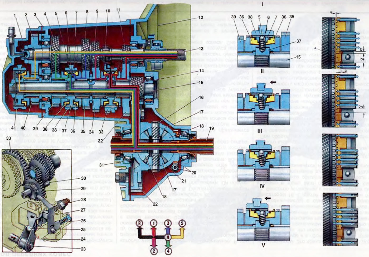
Figure 20 Gearbox operation diagram: 1. Back cover; 2. V-gear drive gear; 3. Gearbox housing; 4. IV gear drive pinion; 5. Locking ball; 6. Lock spring; 7. Retainer cracker; 8. Third gear drive pinion; 9. Second gear drive pinion; 10. Reverse drive pinion; 11. 1st gear drive pinion; 12. Clutch housing; 13. Primary shaft of the gearbox; 14. Main gear pinion; 15. Secondary shaft; 16. Axis of satellites; 17. Satellite; 18. Half-axle gear; 19. Axle shaft seal; 20. Speedometer drive gear; 21. Differential box; 22. Driven gear of the main transmission; 23. Gear selection rod; 24. Gear selector lever; 25. Three-arm gear selector lever; 26. Reverse fork lock; 27. Reverse fork; 28. Reverse light switch; 29. Reverse intermediate gear; 30. Reverse intermediate gear shaft; 31. Adjusting ring; 32. Driven gear of 1st gear; 33. Sliding clutch for engaging 1st, 2nd and reverse gears; 34. Second gear driven gear; 35. Driven gear of the 3rd gear; 36. Locking ring of synchronizer of III and IV gears; 37. Hub of synchronizer clutch of III and IV gears; 38. Sliding clutch of synchronizer III and IV gears; 39. Driven gear of the 4th gear; 40. Driven gear of the 5th gear; 41. Sliding clutch of the 5th gear synchronizer; A - locking ring protrusion; a, b, c - gaps; I. Scheme of operation of the synchronizer; II. Neutral position; III. Start of the inclusion of the IV gear; IV. Completion of alignment of angular velocities of gear 39 and shaft 15; V. Full engagement of IV gear.
To improve the vehicle's performance and reduce fuel consumption in mechanical step gearboxes, the rational selection of the number of gears, the size of gear ratios, and the improvement of the quality of the gear shifting process are primarily taken into account. The latter is of great importance, since the smoothness of gear shifting ensures increased reliability of vehicle components and reduced driver fatigue. For this purpose, all forward gears in the gearbox are synchronized.
The synchronizer's operating principle is based on equalizing the rotational speeds of the secondary shaft and the freely rotating constant mesh gears on it. The figure on the right shows the synchronizer's operating principle when engaging the fourth gear in the following clutch position:
I. When the clutch 38 is in the neutral position, the crackers 7 of the lock are in the center of the grooves of the hub 37 and do not act on the blocking rings 36. Between the projections A of the blocking ring and the grooves of the hub there is a uniform lateral clearance "b", and between the projections A and the crackers 7 there is a clearance "c" (see "Operation of the synchronizer").
II. When the IV gear is engaged, the sliding clutch, moving towards gear 39, drags crackers 7 along with it, which rest against projections A of the blocking ring, i.e. the gap "c" is selected. With further movement of the clutch, the crackers press the blocking ring against the conical surface of the synchronizer ring of gear 39. Under the action of friction forces between the conical surfaces of the blocking ring and the synchronizer ring and the inertia of the synchronized masses, the blocking ring rotates relative to the hub until the ring projections rest against the side walls of the hub grooves, i.e. the gap "b" is selected, and on the other side it increases twofold.
III. Due to the circumferential displacement of the blocking ring by 1/4 of the pitch, the lateral bevels of the sliding clutch rest against the lateral bevels of the blocking ring, and further axial movement of the sliding clutch 38 ceases until the angular velocities of the gear 39 of the fourth gear and the secondary shaft 15 are equalized. At this moment, the friction of the friction cones of the blocking ring and gear 39 ceases, as a result of which the force pressing the beveled surfaces of the teeth of the clutch and the ring disappears.
IV. The released clutch easily connects to the locking ring crown, and then to the synchronizer crown, connecting it to the hub.
When the gear is fully engaged, the gaps between the crackers and the protrusions A of the locking ring and the grooves of the hub are restored.
The figure on the left shows the torque transmission diagrams when all gears are engaged.
With the gearshift lever in neutral, the engine running and the clutch engaged, the torque from the engine is transmitted through the clutch to the primary shaft 13 of the gearbox. From the leading gears of the primary shaft, the torque is transmitted to the same gears of the secondary shaft, which, not having a direct connection with the secondary shaft, will rotate freely on it. Torque is not transmitted to the main gear and differential.
When the first gear is engaged, the sliding clutch 33 of the synchronizer, moving towards the gear 32, connects the synchronizer ring of the first gear gear with the synchronizer hub, rigidly connected to the secondary shaft. The torque from the gear 32 is transmitted through the clutch to the synchronizer hub and from it to the secondary shaft. Through gears 14 and 22, the torque is transmitted to the differential. The differential box, rotating together with the satellite axis, distributes the torque to the front wheel drives through the teeth of the satellites and half-axle gears.
When the second gear is engaged, clutch 33 connects the driven gear 34 of the second gear to the synchronizer hub, and the torque from gear 34 is transmitted through sliding clutch 33 to the synchronizer hub and to the secondary shaft.
The third and fourth gears are engaged by another synchronizer. When the third gear is engaged, clutch 38 connects gear 35 to the synchronizer hub, and when the fourth gear is engaged, it connects gear 39 to the hub of the same synchronizer. The torque is transmitted to the secondary shaft through the connected gear and hub. Similarly, clutch 41 of the fifth gear synchronizer connects gear 40 to the synchronizer hub, and through it to the secondary shaft.
Reverse gear is engaged when the vehicle is completely stopped. When reverse gear is selected, the gearshift lever is moved to the left until it stops with increased resistance and forward. In this case, the intermediate gear 29 of the reverse gear connects the leading gear of the primary shaft of the reverse gear with the toothed rim of the sliding clutch 33 of the synchronizer of the first and second gears. Due to the intermediate gear, the transmitted torque changes its direction. Simultaneously with the engagement of the reverse gear, the reverse light is turned on, since the fork 27 presses the rod of the reverse gear switch, and the lamp circuit is connected to the current source.
A clear separation of the III-IV gear lines and reverse gear is achieved by a spring lock 44 (see figure 17), which ensures a sharp increase in the force required to select the reverse gear at the beginning and a drop at the end of the selection stroke.
Lubrication of the gearbox parts is carried out by splashing oil on the toothed rims of the gears. To improve the lubrication conditions of the secondary shaft gear needle bearings, radial holes are drilled in the gears between the toothed rims, through which oil is supplied to the bearings.