




The diaphragm type power mode economizer is connected by fuel channel 10 (figure 47) with the main dosing system of the first chamber. The cavity under the diaphragm 7 is connected by air channel 6 to the under-throttle space. The economizer jet 9 is installed in the fuel channel. The internal cavity under the diaphragm is connected through ball valve 8 to the float chamber.
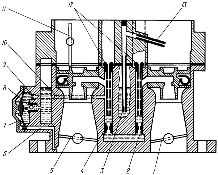
Figure 47. Scheme of economizer and economizer of power modes:
1 - throttle valve of the second chamber; 2 - main fuel jet of the second chamber; 3 - fuel jet economizer with tube; 4 - main fuel jet of the first chamber; 5 - first chamber throttle valve; 6 - vacuum supply channel; 7 - economizer diaphragm; 8 - ball valve; 9 - fuel jet economizer; 10 - fuel channel; 11 - air damper; 12 - main air jets; 13 - economizer injection tube.
The power mode economizer operates at a certain vacuum under the throttle valve 5. The ball valve 8 is closed while the diaphragm is held by the vacuum. When the vacuum decreases, the diaphragm opens the ball valve under the action of the spring. Fuel under the action of the vacuum in the emulsion well of the first chamber comes from the float chamber through the ball valve, fuel jet 9, fuel channel 10 into the emulsion well. This fuel, together with the fuel coming out of the main fuel jet 4, comes through the sprayer into the first mixing chamber, equalizing the composition of the combustible mixture during suction pulsation.
The economizer will also enrich the combustible mixture with a significant opening of the throttle valves, when the vacuum under the throttle valve decreases and the ball valve 8 is open.
Econostat
The econostat is included in the second mixing chamber and comes into operation with the throttle valves fully open at speeds close to maximum. The econostat enriches the combustible mixture to obtain full engine power.
The information is published on the website: VAZbook
The economizer consists of a fuel jet 3 (see figure 47) with a tube, a fuel channel and an injection tube 13, located in the air branch pipe of the second chamber.
With the throttle valves fully open and the crankshaft at maximum speed, the vacuum at the outlet of the injection tube 13 increases so much that the fuel from the float chamber is sucked through the nozzle and tube into the mixing chamber, enriching the combustible mixture.