
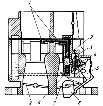
Pic. 49. Scheme of the accelerator pump:
1 - sprayers; 2 - ball fuel supply valve: 3 - pump diaphragm; 4 - pusher; 5 - drive lever; 6 - pump drive cam; 7 - throttle valve of the first chamber; 8 - check ball valve; 9 - throttle valve of the second chamber.
With a sharp opening of the throttle valve 7, the cam 6 presses the lever 5 and through the spring in the pusher 4 acts on the diaphragm 3, overcoming the resistance of the return spring. The diaphragm supplies fuel through the fuel supply ball valve 2 and injects it through the atomizer 1 into the first and second mixing chambers, enriching the combustible mixture. During the reverse stroke of the diaphragm, under the action of a return spring, fuel is sucked from the float chamber through the check ball valve 8 into the working cavity of the accelerator pump. The amount of fuel injected by the accelerator pump is not adjustable and depends only on the cam profile.