
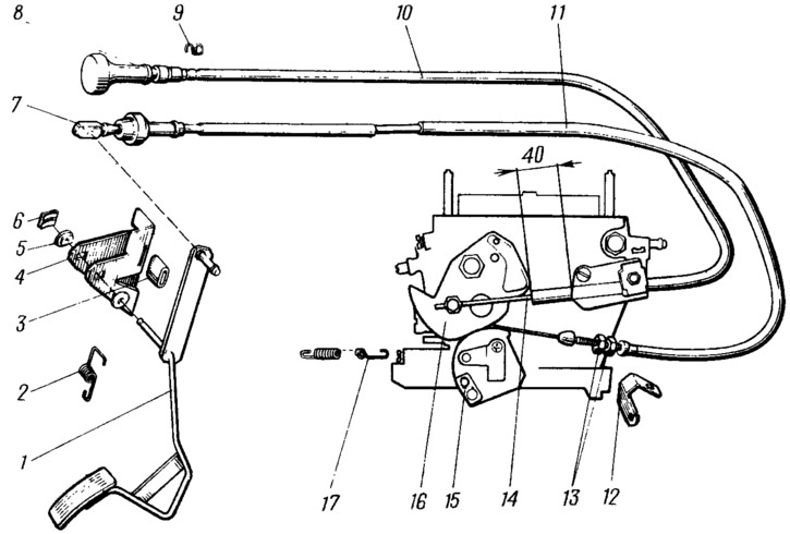
Pic. 51. Carburetor control drive:
1 - throttle control pedal; 2 and 17 - return springs; 3 - pedal stop gasket; 4 - bracket; 5 - bushing; 6 - locking bracket; 7 - cable tip; 8 - air damper control handle; 9 - retaining spring; 10 - thrust shell; 11 - cable sheath; 12 - adjusting tip bracket; 13 - adjusting nuts; 14 - air damper drive rod; 15 - throttle control sector; 16 - air damper control lever.
The upper end of the lever is connected by a cable to sector 15 of the throttle control. The rear tip 7 of the cable has a rubber damper that absorbs vibrations transmitted from the power unit to the pedal. The front tip of the cable is fastened with adjusting nuts 13 in the bracket 12. The cable is placed in the sheath 11.
With the throttle valves fully closed, the cable must be taut. The tension is provided by adjusting nuts 13 of the front tip.
The impact of the driver on the pedal is transmitted through the cable to the throttle control sector. The pedal and throttle valves are returned to their original position by springs 2 and 17. With fully open throttle valves (pedal fully depressed) pedal 1 should not reach the stop by 5...10 mm. If necessary, the bracket with an emphasis is bent.
The carburetor air damper is controlled by handle 8 located under the instrument panel. The handle is connected by a rod 14 to the lever 16 of the air damper control. The shell 10 of the thrust is attached to the carburetor bracket. When the handle is pulled out, the air damper closes; when the handle is pushed in, it opens.