




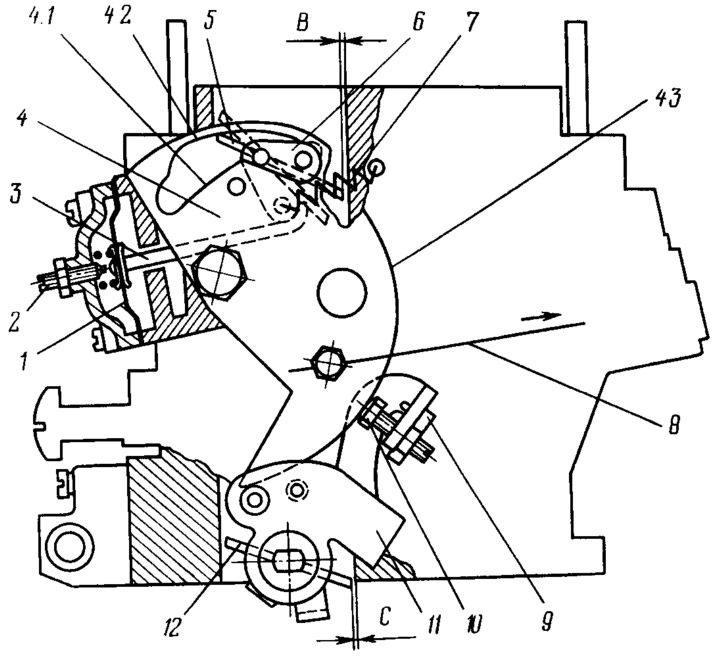
Figure 50. Carburetor starting device:
1 - diaphragm; 2 - adjusting screw; 3 - diaphragm rod; 4 - air damper control lever; 4.1 - lower profile of the groove of the lever 4 for limiting the maximum opening of the air damper; 4.2 - upper groove profile providing mechanical opening of the air damper; 4.3 - edge of lever 4 to provide starting clearance of the first chamber throttle valve; 5 - air damper; 6 - air damper lever; 7 - air damper return spring; 8 - air damper drive handle rod; 9 - adjusting screw stopper; 10 - first chamber throttle valve opening adjusting screw; 11 - throttle control lever; 12 - first chamber throttle valve.
When turning the air damper control lever 4 counterclockwise, the expanding groove between the internal profiles 4.1 and 4.2 releases the pin of the air damper lever 6 and the damper will be held in the closed position by the return spring 7. At the same time, due to the significant vacuum under the throttle valve and in the mixing chamber, the main metering system, the idle system and the transition system of the first chamber will operate, preparing a rich combustible mixture.
The air damper axis is offset, so after starting and increasing the engine speed, the damper will open slightly due to the air flow, stretching the spring 7, which will ensure some leaning of the mixture.
The increase in vacuum in the sub-throttle space acts on the diaphragm U, as a result of which the air damper is forcibly opened by means of the rod 3. The adjusting screw 2 allows you to regulate the magnitude of this opening. Its maximum value during engine start-up and warm-up depends on the intermediate positions of the air damper control lever 4, i.e. on the width of the groove of this lever, and on the position of the adjusting screw 2.
As the engine warms up, gradually move the air damper control handle forward, and lever 4 with profile 4.2 opens the air damper.
The original can be viewed on the portal (VAZBOOK.RU)