




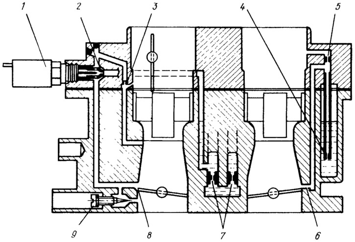
Figure 48. Idle system and transition systems diagram:
1 - electromagnetic shut-off valve; 2 - idle fuel jet; 3 - idle air jet; 4 - fuel jet of the transition system of the second chamber; 5 - air jet of the transition system of the second chamber; 6 - outlet of the transition system of the second chamber; 7 - main fuel jets; 8 - first chamber transition system slit; 9 - adjusting screw for idle mixture quality (composition).
When the engine is idling, the throttle valves are closed, the vacuum from under the throttle valve of the first chamber will be transmitted to all channels of the system. Under the action of the vacuum, fuel comes from the float chamber through the main fuel jet 7 of the first chamber and the emulsion well, rises along the fuel channel to the fuel jet 2 (in this case the jet is not closed by the electromagnetic valve 1), passes through the jet, mixes with air from jet 3 and exits through the emulsion channel in the form of an emulsion under the adjusting screw 9 of the mixture quality (composition) into the throttle space. Additionally, air from the mixing chamber is sucked in along the path of the emulsion through the gap 8. The mixture quality (composition) at idle is adjusted by screw 9, and the mixture quantity is adjusted by the mixture quantity screw, when screwed in, the throttle valve opens slightly.
When the ignition is turned off, electromagnetic valve 1 is turned off, the valve needle, under the action of the spring, closes fuel jet 2 and does not allow the system to operate with the ignition off when the engine overheats.
Transitional systems
The transition systems of the first and second chambers ensure a smooth transition from one engine operating mode to another at the moment the throttle valve of the first chamber begins to open, and then the second chamber.
The transition system of the first chamber includes a slit 8 (see figure 48), located slightly above the closed throttle valve, and elements of the idle system. At the moment the throttle valve begins to open, the gap is under vacuum. The emulsion begins to flow not only under screw 9, but also through the gap under the throttle valve, preventing the depletion of the combustible mixture. The emulsion consumption increases, compensating for the increase in air consumption in the carburetor mixing chamber. As the throttle valve opens, the opening of the gap increases and, accordingly, the amount of emulsion increases until the main metering system starts working, thereby eliminating "dips" in engine operation.
The transition system of the second chamber consists of a fuel jet 4 with a tube, an air jet 5, an emulsion channel with outlet holes 6 above the throttle valve in the closed position. The air jet is connected by a channel to the air branch pipe of the second chamber. At the moment the throttle valve begins to open, the holes 6 enter the vacuum zone. Fuel is sucked from the float chamber through the jet, rises up the tube, mixes with air from the air jet and in the form of an emulsion through the emulsion channel exits through the holes under the throttle valve of the second chamber, ensuring a smooth transition to the operation of the main metering system.
The original is available on the website VazBook