




Contents: Removal the carburetor ↓ Disassembling the carburetor ↓ Cleaning carburetor parts ↓ Assembly and installation of the…↓
Wash the parts with the carburetor removed and disassembled. Remove and install the carburetor only on a cold engine.
Remove cover 6 (see figure 42) air filter and filter element. Loosen the nuts securing the filter housing 4 to the carburetor. Remove the housing together with the thermostat 3, disconnect the corrugated hose 2 and the crankcase ventilation exhaust hose, having first loosened the fastening clamps.
Removal the carburetor
Disconnect from sector 15 (see figure 51) throttle drive cable and return spring 17, and also disconnect rod 14, casing 10 of the air damper drive rod from the carburetor. Unscrew the fastening screw and remove the carburetor heating unit. Disconnect the electric wires of the limit switch and electromagnetic shut-off valve from the carburetor, as well as the vacuum take-off and crankcase ventilation hoses. Unscrew the carburetor fastening nuts, remove the carburetor, heat shield, heat-insulating spacer and close the outlet opening of the intake manifold with a plug.
Disassembling the carburetor
Loosen the screws securing the carburetor cover and carefully remove it so as not to damage the gasket, float, economizer tubes and the transition system of the second chamber.
Disassemble the carburetor cover, for which carefully push out the axle 1 with a mandrel (figure 52) float 3 from the racks and, without damaging the float tongues, remove it. Remove cover gasket 4, unscrew needle valve seat 2, unscrew fuel supply pipe 11 and remove fuel filter 12. Unscrew the housing of the idle fuel jet with electromagnetic shut-off valve 10 and remove jet 9. Unscrew axle 19, remove ball 17 with spring, remove air damper control lever 18, disconnect the air damper control lever spring. If necessary, unscrew the air damper fastening screws, remove damper 15 and axle 16.
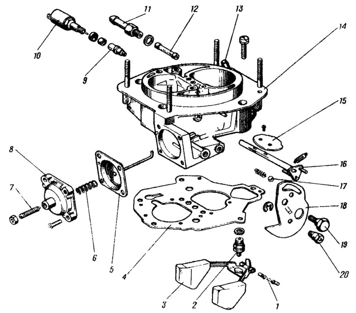
Figure 52. Carburetor cover parts:
1 - float axis; 2 - needle valve; 3 - float; 4 - gasket; 5 - diaphragm of the starting device with a rod, 6 - spring; 7 - adjusting screw; 8 - Starter cover; 9 - idle fuel jet; 10 - electromagnetic clans; 11 - fuel supply pipe to the carburetor; 12 - fuel filter; 13 - fuel drain pipe; 14 - carburetor cover; 15 - air damper; 16 - air damper shaft with lever; 17 - air damper control lever locking ball; 18 - air damper control lever; 19 - lever axis; 20 - air damper drive rod mounting sleeve.
Disassemble the diaphragm starting device by removing cover 8 together with adjusting screw 7. Remove spring 6 and diaphragm 5 with rod.
Disassemble the carburetor body (figure 53), to do this, remove cover 3 of the accelerator pump with lever 2 and diaphragm 1. Remove nozzles 10 of the accelerator pump and nozzles 11 of the first and second chambers of the main metering systems. Remove the accelerator pump nozzles only by the housing. Unscrew the nut of the first chamber throttle shaft, remove cam 4 of the accelerator pump drive and washer. Unscrew the fastening screw, remove the electric wire from the adjusting screw 30 of the idle mixture quantity and unscrew the screw 30. Use a corkscrew to remove plastic plug 26 and unscrew the adjusting screw 28 of the quality (composition) of the idle mixture. Remove cover 5 of the power mode economizer, diaphragm 6 and spring. Unscrew fuel jet 7 of the power mode economizer. Unscrew the main air jets 12 with emulsion tubes and the main fuel jets 13 of the main metering systems.
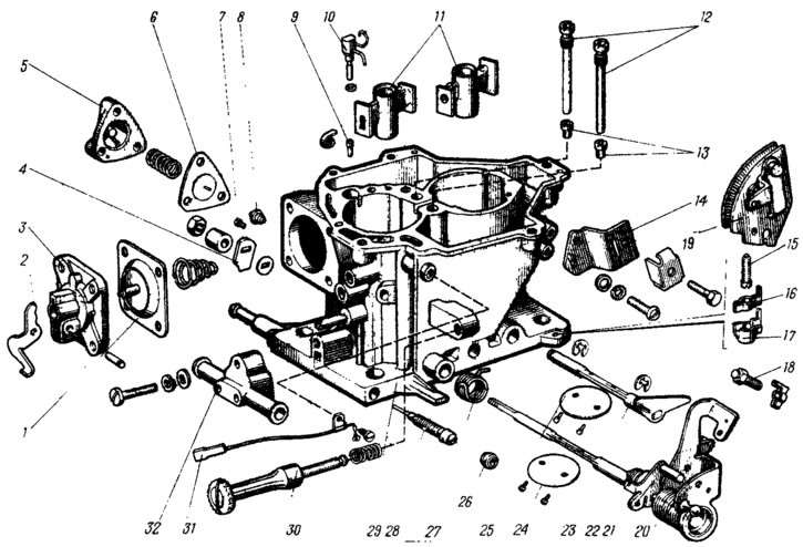
Figure 53. Carburetor body parts:
1 - accelerator pump diaphragm; 2 - accelerator pump drive lever; 3 - lid; 4 - accelerator pump drive cam; 5 - power mode economizer cover; 6 economizer diaphragm; 7 - fuel jet economizer; 8 - economizer valve; 9 - accelerator pump check valve; 10 - accelerator pump nozzles with fuel supply valve; 11 - Sprayers; 12 - main air jets with emulsion tubes; 13 - main fuel jets; 14 - bracket for fastening the air damper drive rod casing; 15 - adjusting screw of the second chamber; 16 - adjusting screw stopper: 17 - stopper cap; 18 - first chamber throttle valve opening adjusting screw; 19 - carburetor throttle control sector; 20 - first chamber throttle shaft with drive levers; 21 - second chamber locking lever; 22 - locking lever spring; 23 - second chamber throttle shaft with lever; 24 - first chamber throttle valve; 25 - second chamber throttle valve; 26 - plug for adjusting screw of mixture quality (composition); 27 - return spring of the second chamber throttle actuator lever; 28 - adjusting screw for idle mixture quality (composition); 29 - carburetor body; 30 - idle mixture quantity adjusting screw; 31 - electric wire of the forced idle economizer limit switch; 32 - carburetor heating unit.
If necessary, unscrew the first chamber throttle valve mounting screws, remove the valve and remove the axle 20 together with the drive levers. After removing the lock washer and unscrewing the second chamber throttle valve mounting screws, remove the valve and remove the valve axle. Remove the bearings of the first and second chamber throttle valve axles.
Cleaning carburetor parts
Wash the carburetor fuel filter in gasoline and blow it with compressed air. Check the condition of the filter. If the filter or fuel supply pipe is damaged, replace it with new ones.
Wash the float mechanism parts in gasoline, check their condition. The sealing surface of the needle valve and its seat must not have any damage that would compromise the valve's tightness. The valve must move freely in its seat, and the ball must not hang. The float weight must not exceed 6.23 g. Replace faulty parts with new ones.
Clean the carburetor cover and all holes and channels in it from dirt and oil. Wash the cover in acetone or gasoline and blow it with compressed air. Inspect the sealing surfaces of the cover. If there is damage, replace the cover with a new one.
Clean all parts of the starting device, wash with gasoline and blow with compressed air. Inspect the parts, replace damaged ones.
Clean the jets and emulsion tubes from dirt and resinous compounds, wash them with acetone or gasoline and blow them with compressed air. Do not clean the jets with a metal tool or wire, or wipe the jets and other parts of the carburetor with cotton wool, cloth or rags, as lint can clog the jets and channels. In case of severe clogging, you can clean the jets with a soft wood needle moistened with acetone.
Clean the carburetor body from dirt and oil. Wash its channels with acetone or gasoline and blow with compressed air.
The parts of the accelerator pump should also be washed in gasoline and blown with compressed air. Check the ease of movement of the ball in the sprayer and the mobility of the elements of the accelerator pump (lever, diaphragm parts). No jamming is allowed. The diaphragm must be undamaged.
Assembly and installation of the carburetor
The carburetor is assembled in the reverse order. In this case, pay attention to the mobility of the float on the axis, ease of movement of the needle valve. In order not to mix up the jets during assembly, it is necessary to look at the marking of the jets and, when installing them, follow the table of basic data given earlier.
After tightening the screws securing the throttle valves to the axles, caulk the screws, preventing deformation of the axles.
When assembling the accelerator pump, it is necessary to first tighten the cover mounting screws, press the drive lever until it stops, tighten the screws and release the lever.
Install the carburetor in the reverse order. Before installation, check the flatness and cleanliness of the surfaces connecting the intake manifold to the carburetor. Do not tighten the fastening nuts of a hot carburetor.
After installing the carburetor, adjust its control drive, put the air filter in place and adjust the engine idle speed.