




Contents: Adjusting the starting device ↓ Adjusting the carburetor drive ↓ Adjusting engine idle speed ↓ Checking the forced idle economizer ↓ Checking the operation of the second…↓
Adjusting the starting device
When turning lever 4 (see figure 50) control of the air damper 5 to the stop counterclockwise, the air damper should be completely closed under the action of the spring 7. If the damper is not closed, eliminate the cause of the jamming. With the air damper completely closed, manually press the rod 3 of the starting device until it stops. In this case, the air damper 5 should open by the amount B (see table 2). If necessary, adjust this gap with adjusting screw 2.
The throttle valve 12 of the first chamber with the air damper fully closed should be slightly open by the value C (see table 2). This gap must be adjusted with screw 10.
Adjusting the carburetor drive
With pedal 1 fully depressed (see figure 51) throttle control, the throttle valve of the first chamber should be fully open and sector 15 should not have any additional travel. When the pedal is released, the throttle valve should be fully closed. If this is not the case, adjust the position of the pedal and throttle valve using adjusting nuts 13 on the front end of the drive cable. The drive should operate without jamming.
In the air damper drive, secure the casing 10 of the rod 14 so that the casing protrudes beyond the carburetor bracket by 40 mm, as shown in the figure. Secure the rod 14 to the air damper control lever 16 so that when the handle 8 is pulled out, the damper is completely closed, and when the handle is recessed, it is completely open.
Adjusting engine idle speed
The idle speed adjustment system has an adjusting screw 2 (figure 55) quality (composition) of the mixture and adjusting screw 1 of the quantity of the mixture. To access adjusting screw 2, it is necessary to break plug 4 with a corkscrew-type tool.
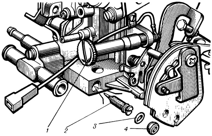
Figure 55. Idle speed adjustment screws:
1 - mixture quantity adjustment screw; 2 - mixture quality (composition) adjustment screw; 3 - sealing ring: 4 - adjusting screw plug.
Idle speed adjustment should be performed on a warm engine (coolant temperature 90...95°C) with adjusted valve timing clearances, with the advance angle set correctly and with the air damper fully open.
Using the mixture quantity adjusting screw 1, set the engine crankshaft speed within 750...800 rpm on the stand tachometer. Then, using the mixture quality (composition) adjusting screw 2, achieve a carbon monoxide (CO) concentration (reduced to 20°C and 760 mm Hg) in the exhaust gases within 0.5...1.2% at the given position of screw 1.
Use screw 1 to restore the crankshaft speed to 750...800 rpm. If necessary, use adjusting screw 2 to restore the CO concentration to 0.5...1.2%.
After completing the adjustment, sharply press the throttle pedal and release it; the engine should increase the crankshaft speed without interruption, and should not stall if it decreases. If the engine stops, use screw 1 to increase the crankshaft speed within 750...800 rpm.
Install a new plastic plug 4 into the hole for the mixture quality adjusting screw 2.
Checking the forced idle economizer
Checking the forced idle economizer consists of checking the operation of the electromagnetic shut-off valve of the carburetor (see chapter "Carburetor electromagnetic valve control system"; section "Electrical equipment").
Checking the operation of the second chamber locking mechanism of the carburetor
Turn the air damper control lever counterclockwise until the damper is completely closed. Then turn sector 19 (see figure 53) control the throttle valves until the first chamber valve is fully opened, while the second chamber throttle valve must remain in the closed position.
Turn the air damper control lever clockwise and the throttle control sector until they are fully open. If the second chamber throttle valve does not open, eliminate the malfunction. The cause may be the jamming of the second chamber lock lever 21 or the disconnection of the lock lever spring 22.