
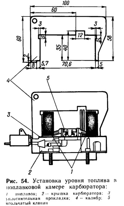
Correct installation of float 1 (pic. 54) check with gauge 4, for which the cover 2 of the carburetor is installed horizontally with the float up and the gauge is placed perpendicular to the cover. There must be a gap of no more than 1 mm between the gauge and the float from above and from the sides. If necessary, it is adjusted by bending the tongue and float levers. The bearing surface of the tongue must be perpendicular to the axis of the needle valve 5 and must not have dents or nicks.
If no gauge is available, the fuel level can be checked by removing the float chamber cover. To do this, first manually fill the float chamber with fuel, disconnect the fuel supply hose to the carburetor and remove the air filter and carburetor cover. Measure the fuel level in the chamber with a ruler from the upper plane of the carburetor body, which should be 23.5... 27 mm (the true fuel level in the float chamber with the carburetor cover installed is higher due to the lower part of the float being immersed in the fuel). If necessary, the fuel level can be changed by bending the float tongue. It is necessary to ensure that the float does not touch the walls of the float chamber. At each next check of the fuel level, first remove the fuel from the float chamber, install the carburetor cover, connect the fuel supply hose and fill the float chamber using the manual fuel primer.