




Disassembly
1. Remove the cylinder head (see "Cylinder head - removal and installation").
2. Remove the oil receiver (see "Oil receiver - removal").
3. Remove the oil pump (see "Oil pump - removal, disassembly, assembly and installation").
4. Remove the pressure and driven disks from the flywheel (see "Slave and pressure plates of the clutch - replacement").
5. Remove the knock sensor from the cylinder block (see "Knock sensor (DS) - removal and testing").
6. Remove the flywheel (see "Flywheel - removal, installation, replacement").
7. Using a 10 mm socket wrench, unscrew the six bolts securing the rear crankshaft oil seal holder.
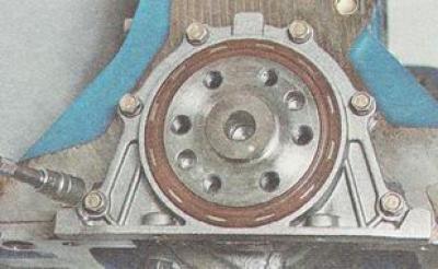
8. Remove the holder with the crankshaft oil seal.
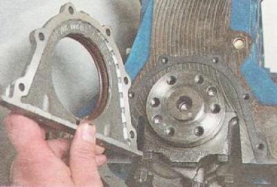
Note: There is a gasket installed under the crankshaft oil seal retainer.
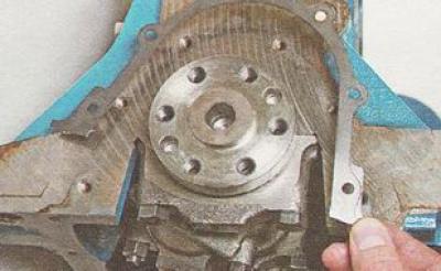
9. Remove four pistons with connecting rods from the cylinder block (see items 1-9 "Piston rings - replacement").
10. Using a 17 mm socket wrench, unscrew two bolts securing the five main bearing caps.
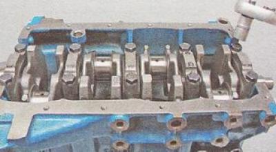
11. Remove the main bearing caps.
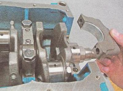
12. Remove the lower main bearing shells from the covers.
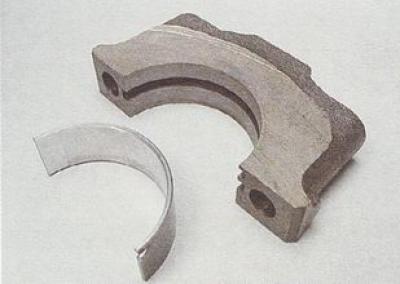
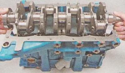
13. Remove the crankshaft from the cylinder block.
14. From the grooves of the third support we remove two half rings - thrust bearings for the axial movement of the crankshaft.
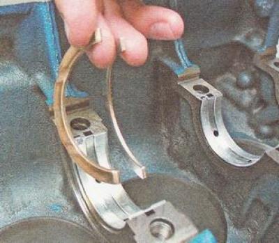
15. Remove the upper main bearing shells from the cylinder block supports.
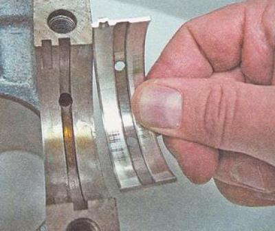
Checking the details
1. Wash the cylinder block from dirt and deposits with a special detergent, diesel fuel or kerosene, blow out the oil channels.
2. Using thin copper wire, clean the outlet holes of the oil injectors.
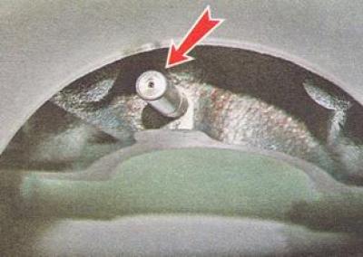
3. Wipe the cylinder block dry and inspect it. Cracks and chipping of metal are unacceptable.
4. We measure the inner diameter of the cylinders with a nutrometer (see point 2 "Piston and connecting rod - replacement").
Note. The degree of wear of each cylinder can be determined by the difference in the nutrometer readings in different belts. If the wear exceeds 0.15 mm, the block should be bored to fit the repair dimensions of the pistons (see point 1 "Piston and connecting rod - replacement").
5. Using a micrometer, measure the main and connecting rod journals of the crankshaft.
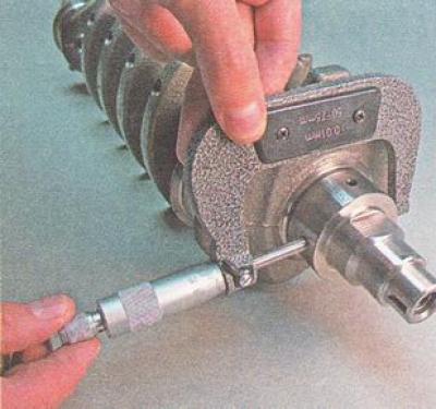
The crankshaft is subject to replacement or grinding if the wear of its journals is more than 0.03 mm or the ovality of the journals is more than 0.03 mm, or there are burrs and scratches on the crankshaft journals. It is possible to grind the crankshaft journals with a reduction in their diameter by 0.25 mm; 0.5 mm; 0.75 mm and 1.00 mm.
Assembly
Recommendation. If the engine cylinders have been bored, it is necessary to wash the cylinder block with diesel fuel or kerosene and blow it with compressed air. After grinding the engine crankshaft journals, remove the plugs of the channel outlets. It is also necessary to wash the crankshaft with kerosene and blow out the crankshaft channels with compressed air.
Warning: Install new plugs into the crankshaft oil channel holes.
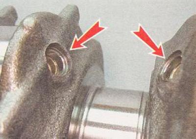
Note. Before assembling the engine, select the appropriate rings, pins and pistons (see item 2 "Piston and connecting rod - replacement"), as well as crankshaft bearing shells (see above).
1. Degrease the bearing shell seats in the bearing supports and caps.
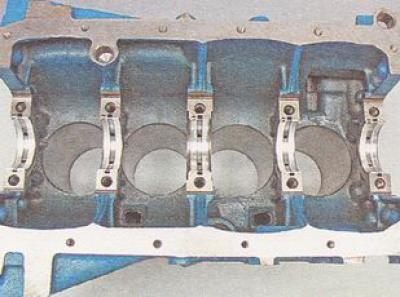
2. Place the inserts with grooves into the support sockets.
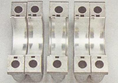
3. Place the liners without grooves into the main bearing caps.
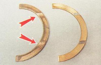
4. We install thrust half rings in the grooves of the third main bearing. On the front side - steel-aluminum (on the inner side - white, and on the outer side - yellow), on the rear - metal-ceramic (yellow on both sides).
Note. Crankshaft half rings are manufactured with a nominal thickness and a thickness increased by 0.127 mm. The axial displacement of the crankshaft should be within 0.06-0.26 mm.
5. Install the crankshaft half rings with the grooves facing outward (to the crankshaft cheeks).
6. Lubricate the crankshaft journals and bearings with clean engine oil.
7. Place the crankshaft in the cylinder block supports and install the main bearing caps.
Note: The bearing numbers (1 through 5) are marked on the main bearing caps. The fifth main bearing cap is marked with two marks spaced apart from each other on the cap.
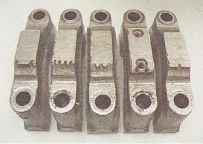
When installing the cover into the block, the marks should face the side of the block on which the oil dipstick is installed.
8. Tighten the main bearing cap bolts with a torque wrench to 68.31-84.38 N·m (6.97-8.61) kgf·m.
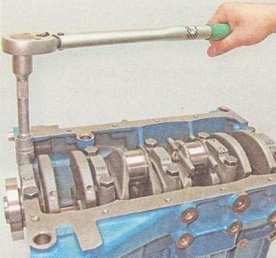
Recommendation. When tightening the main bearing caps, make sure that the crankshaft rotates freely. To do this, after tightening the bolts of the next cap, turn the crankshaft. It should rotate with the force of your hands. If the crankshaft rotates with difficulty or is jammed, the bearing caps may be mixed up or the liners may be incorrectly selected.
9. Assemble the connecting rod and piston group (see "Piston and connecting rod - replacement").
10. Install the pistons into the block cylinders (see "Piston rings - replacement").
Recommendation: When tightening the connecting rod caps, check the free rotation of the crankshaft as described above. Since more effort is required to rotate the crankshaft together with the pistons, a flywheel should be installed on the shaft and the shaft should be turned by it.
The order of further engine assembly depends on the form in which the engine needs to be installed on the car - assembled or partially disassembled. In any case, the engine should be assembled in the reverse order of disassembly.