
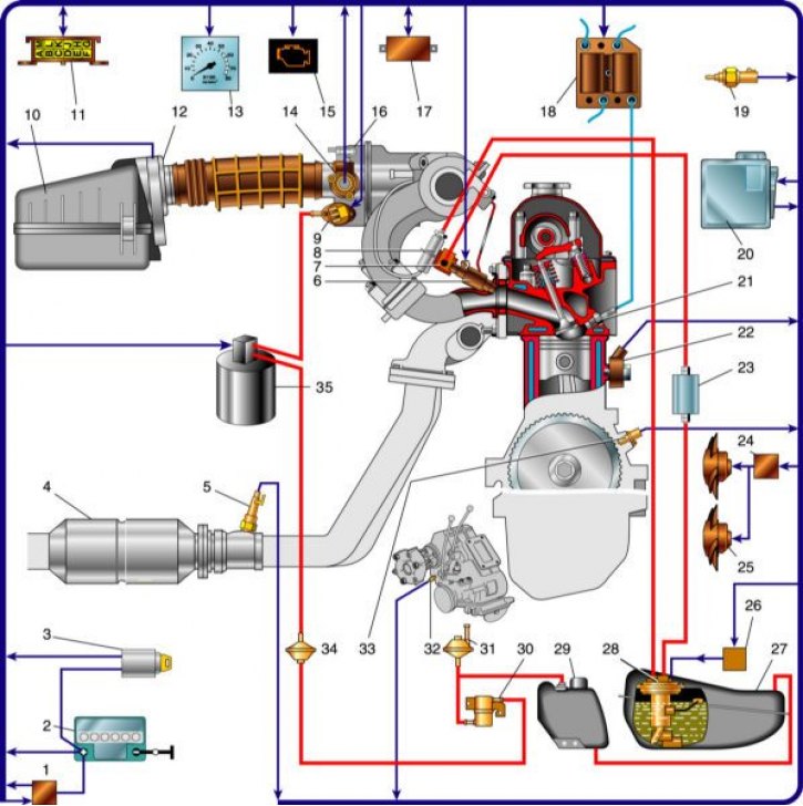
The layout of the elements of power supply and engine control systems: 1 - ignition relay; 2 - storage battery; 3 - ignition switch; 4– neutralizer; 5 – oxygen concentration sensor; 6 - nozzle; 7 - fuel rail; 8 - fuel pressure regulator; 9 - idle speed regulator; 10 - air filter; 11 - diagnostic socket; 12 - mass air flow sensor; 13 - tachometer; 14 - throttle position sensor; 15 - lamp for monitoring the operation of the engine management system; 16 - throttle assembly; 17 - immobilizer control unit (APS); 18 - ignition module; 19 - coolant temperature sensor; 20 - controller; 21 - spark plug; 22 - knock sensor; 23 - fuel filter; 24 - fan switching relay; 25 - electric fans of the cooling system; 26 - relay for turning on the electric fuel pump; 27 - fuel tank; 28 - electric fuel pump with fuel gauge sensor; 29 - gasoline vapor separator; 30 - gravity valve; 31 - safety valve; 32 - speed sensor; 33 - crankshaft position sensor; 34 - two-way valve; 35 - adsorber.
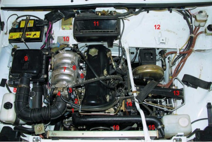
Location of elements of power supply and engine control systems: 1 - coolant temperature sensor; 2 - idle speed regulator; 3 - throttle position sensor; 4 - throttle assembly; 5 - fuel rail with injectors and fuel pressure regulator; 6 - knock sensor (located on the cylinder block under the exhaust manifold - not visible in the photo); 7 - receiver; 8 - mass air flow sensor; 9 - air filter housing; 10 - oxygen concentration sensor (located on the downpipe - not visible in the photo); 11 - speed sensor (located on the transfer case - not visible in the photo); 12 - controller, diagnostic connector and fuses of the fuel injection system (located in the passenger compartment - not visible in the photo); 13 - fuel filter; 14 - ignition module; 15 - adsorber of the fuel vapor recovery system; 16 - crankshaft position sensor.
The VAZ-21214 engine is equipped with a multiport fuel injection system (separate injector for each cylinder) with electronic control.
Attention! When servicing or repairing the engine management system, always turn off the ignition. When welding, disconnect the controller from the wiring harness. The controller contains electronic components that can be damaged by static electricity, so do not touch the terminals with your hands. Before drying the car in a drying chamber (after painting) remove the controller. With the engine running, do not disconnect or adjust the electrical connectors (including battery terminals). Do not start the engine if the battery terminals and «masses» on the engine and body are loose or dirty.
Injection controller (Control block) is a special purpose minicomputer. It contains three types of memory - RAM (RAM), Programmable Read Only Memory (PROM) and electrically programmable memory (EPROM).
RAM is used by the computer to store current information about the operation of the engine and process it. Fault codes are also stored in the RAM. This memory is volatile, i.e. when the power is turned off, its contents are erased.
EPROM contains the actual program (algorithm) computer performance and calibration data (settings). Thus, the PROM determines the most important parameters of the engine operation: the nature of the torque and power curves, fuel consumption, etc. EPROM is non-volatile, i.e. its content does not change when the power is turned off. The PROM is installed in a slot on the controller board and can be replaced separately (if the controller fails, the serviceable EPROM can be rearranged to a new controller). The EEPROM stores the immobilizer codes when «learning» keys (see car service book). This memory is also non-volatile.
The controller is located in the passenger compartment, on the side panel in the driver's foot area.
Injection sensors give the controller information about the parameters of the engine (except vehicle speed sensor), on the basis of which he calculates the moment, duration and order of opening of the injectors, the moment and order of sparking. In case of failure of individual sensors, the controller switches to bypass operation algorithms; this may degrade some engine parameters (power, efficiency, efficiency), but movement with such faults is possible. The only exception is the crankshaft position sensor, if it malfunctions, the engine cannot work. Also, the engine will not work if several sensors fail at the same time. Sensors are non-repairable; if they fail, they are replaced.
crankshaft position sensor installed in the hole of the camshaft drive cover bracket. It gives the controller information about the angular position and speed of the crankshaft. The sensor is an inductor; it reacts to the passage of the teeth of the master disk near the sensor core. Two adjacent teeth on the disc are cut off, forming a cavity. When it passes, the sensor generates the so-called «reference» synchronization pulse with each revolution of the crankshaft. The installation clearance between the core and the teeth is 1.0±0.2 mm.
coolant temperature sensor screwed into the exhaust pipe on the cylinder head. It is a thermistor, at a temperature of -40°C, its resistance should be 100 kOhm, at 100°C - 177 Ohm. The controller supplies a stabilized voltage of 5 V to the sensor through a resistor and calculates the composition of the mixture based on the voltage drop. When the sensor fails, the controller switches the electric fans of the cooling system to a constant mode of operation.
Throttle position sensor (TPS) mounted on the throttle axis and is a potentiometer. A stabilized voltage of 5 V is supplied to one end of its winding, and the other is connected to «weight». From the third output of the potentiometer (slider) a signal is received for the controller. To check the sensor, turn on the ignition and, without disconnecting the connector (wires can be pierced with thin needles connected to the terminals of a voltmeter), measure the voltage between «weight» and the output of the slider - it should be no more than 0.7 V. Turning the plastic sector by hand, fully open the throttle and measure the voltage again - it should be more than 4 V. Turn off the ignition, disconnect the connector, connect an ohmmeter between the output of the slider and any of the two the rest. Slowly turn the sector by hand, following the indications of the arrow. There should be no jumps in the entire range of the working stroke. In the event of failure of the TPS, its functions are taken over by the mass air flow sensor. At the same time, the idle speed does not fall below 1200 min-1.
Mass air flow sensor located between the air filter and the intake hose. It consists of two sensors (working and control) and heating resistor. The passing air cools one of the sensors, and the electronic module converts the temperature difference of the sensors into an output signal for the controller. In the event of a failure of the mass air flow sensor, its functions are taken over by the TPS.
Knock sensor bolted to the top of the cylinder block on the right side. The action of the sensor is based on the piezoelectric effect: when a piezoelectric plate is compressed, a potential difference arises at its ends. When knocking, voltage pulses occur in the sensor, according to which the controller regulates the ignition timing. For the correct operation of the sensor, the mounting bolt must be tightened to the recommended torque.
Oxygen concentration sensor (oxygen sensor, lambda probe) installed in the intake pipe of the exhaust system (see Exhaust system). The oxygen contained in the exhaust gases creates a potential difference at the output of the sensor, varying from approximately 0.1 (too much oxygen - lean mixture) up to 0.9 V (little oxygen - rich mixture). Based on a signal from the oxygen sensor, the controller adjusts the fuel supply by injectors to the cylinders so that the composition of the exhaust gases is optimal for the efficient operation of the converter (oxygen sensor voltage about 0.5 V). For normal operation, the oxygen sensor must have a temperature of at least 360°C, therefore, for quick warming up after starting the engine, a heating element is built into the sensor.
The controller constantly outputs a stabilized reference voltage of 0.45±0.10 V to the oxygen sensor circuit. While the sensor is not warmed up, the reference voltage remains unchanged. In this case, the controller controls the injection system without taking into account the voltage on the sensor. As soon as the sensor warms up, it begins to change the reference voltage. Then the controller turns off the heating of the sensor and starts to take into account the signal of the oxygen sensor.
Vehicle speed sensor installed in the transfer case next to the speedometer drive. The principle of its operation is based on the Hall effect. The sensor outputs rectangular voltage pulses to the controller (lower level - no more than 1 V, upper - no less than 5 V) with a frequency proportional to the speed of rotation of the drive wheels.
idle speed controller maintains idle speed within 820–880 min–1 regardless of engine load (in particular, when turning on and off powerful consumers of electricity). It is a stepper motor with a micrometer screw. When the screw moves, the cross section of the bypass air channel between the inlet pipe and the receiver changes (bypassing the throttle). A defective regulator is recommended to be replaced at a service station where there is a device that allows you to control it (sometimes during installation, the protrusion of the adjuster screw needs to be reduced).
Ignition system included in the engine management system. It consists of an ignition module, high voltage wires and spark plugs. During operation, the system does not require maintenance and adjustment. The ignition module is mounted on a bracket attached to three studs at the left front of the engine. It includes two control electronics and two high voltage transformers (ignition coils). Spark plug wires are connected to the outputs of the high-voltage windings of the transformers - to one of the 1st and 4th cylinders, to the other - of the 2nd and 3rd. Thus, the spark simultaneously jumps in two cylinders (1–4 or 2–3) - in one during the compression stroke (working spark), in the other - at the time of release (single). The ignition module is non-separable; in case of failure, it is replaced.
Spark plug - A17DVRM or their analogues, with a noise suppression resistor of 4–10 kOhm and a copper core. The gap between the electrodes is 1.00–1.13 mm.
Four fuses and three relays for the engine management system (most importantly, an electric fuel pump and electric fans of the engine cooling system) located in the cabin under the instrument panel on the left side. The power contacts of all relays are closed by the controller commands. Three 15 A fuses protect the constant power supply circuit of the control unit, the main relay and its circuits, the power contacts of the fuel pump relay and its circuit. A 30 A fuse protects the power contacts of the relay and the power circuit of the electric fans of the engine cooling system. In addition to fuses, a fusible link is provided in the power supply circuit of the engine control system (from terminal «plus» battery to the fuse box of the control system). It is located in the engine compartment and is made in the form of a piece of black wire with a cross section of 1 mm2 (section of the main wire - 6 mm2).