




Warning! The cylinder head is replaced with the bearing housings as a unit, as they are machined together.
You will need: 13, 17, 21 keys, spark plug wrench, screwdriver, round-nose pliers (tweezers), valve spring compression tool.
1. Remove the cylinder head (see "Replacing the cylinder head gasket").
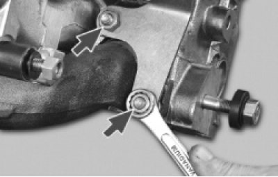
2. Unscrew the two fastening nuts and remove the eye.
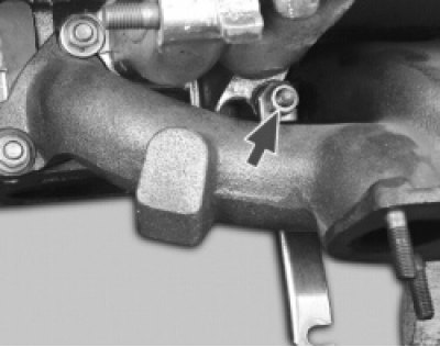
3. Loosen the fastening nut one or two turns and remove the water pump inlet pipe bracket.
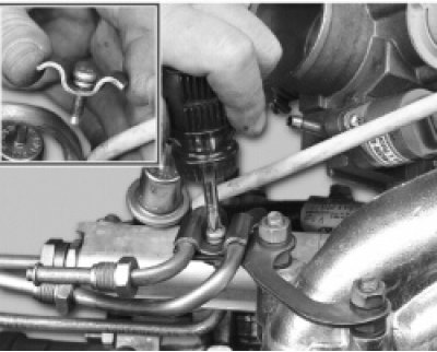
4. Loosen the screw securing the fuel pipe holder and remove the holder.
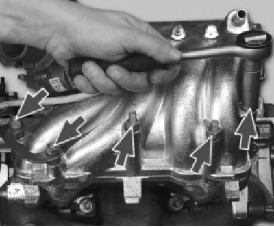
5. Unscrew the three nuts securing the receiver and the two nuts securing the fuel pipe bracket.
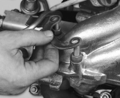
6. Remove the fuel pipe bracket.
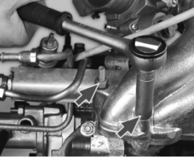
7. Unscrew the remaining two receiver mounting nuts.
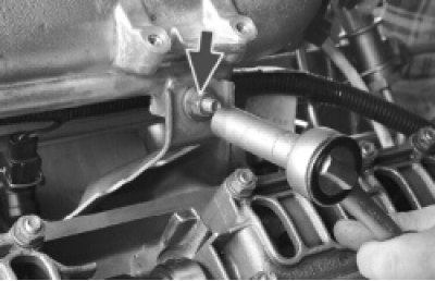
8. Loosen the receiver bracket mounting nut.
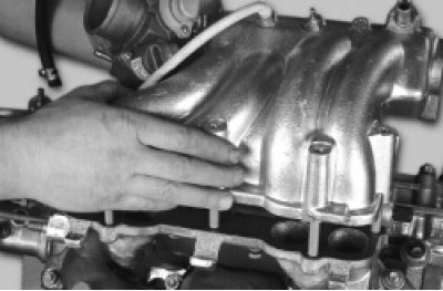
9. Remove the receiver.
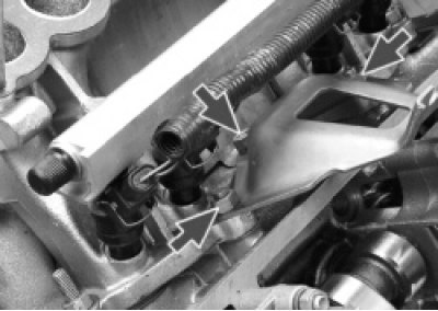
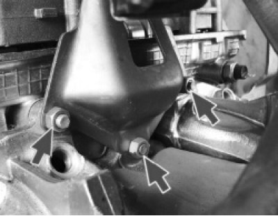
10. Unscrew the three nuts securing the receiver bracket and remove the bracket.
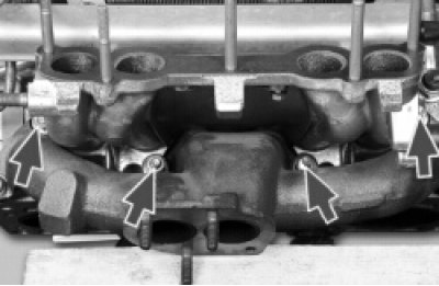
11. Unscrew the four nuts securing the intake pipe.
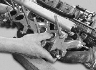
12. Remove the intake pipe.
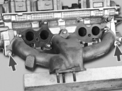
13. Unscrew the two exhaust manifold mounting nuts and remove the manifold.
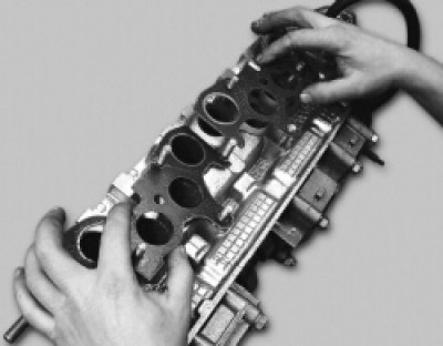
14. Carefully remove the two intake manifold and exhaust manifold gaskets.
Helpful advice: Even if the gaskets are not damaged and are not too tightly compressed, it is better to replace them and not reuse them.
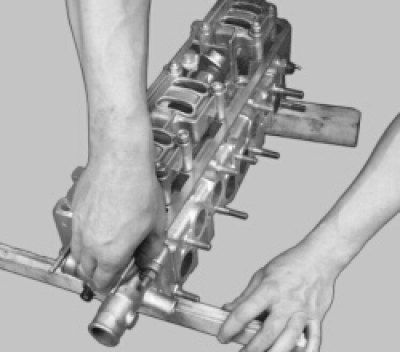
15. Install the cylinder head with the bearing housings facing up, placing wooden spacers underneath it to avoid damaging the valves.
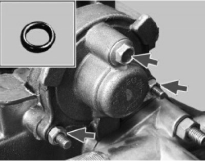
16. Unscrew the two nuts and bolt securing the rear cylinder head cover and remove the cover. Note that there is a sealing ring installed under the bolt head.
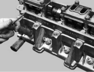
17. Remove the spark plugs.
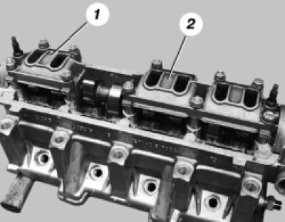
18. Evenly unscrew the four nuts securing the front 1 and six nuts securing the rear 2 camshaft bearing housings and remove the washers. Then remove both housings.
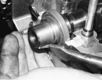
19. If the key does not fit tightly in the camshaft groove, remove it so as not to lose it.
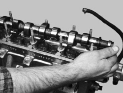
20. Remove the camshaft from the cylinder head.
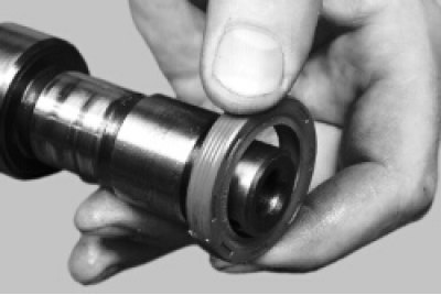
21. Remove the oil seal from the camshaft.
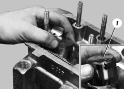
22. Remove the valve lifters together with the adjusting washers.
Warning! After removing each tappet, mark it and the adjusting washer with a serial number so that they can be installed in their proper places during assembly. Do not remove the adjusting washers from the tappets unless necessary to avoid mixing them up.
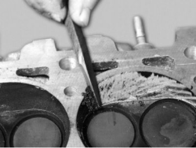
23. Clean the combustion chambers from carbon deposits. Inspect the cylinder head. If there are cracks or traces of burnout in the combustion chambers, replace the head. Remove burrs and nicks on the plane of the cylinder head.
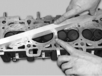
24. Check the flatness of the surface adjacent to the cylinder block. To do this, place a ruler with its edge on the surface of the head, first in the middle along, then diagonally, and measure the gap between the plane of the head and the ruler with a feeler gauge. Replace the head if the gap exceeds 0.1 mm.
25. To check the tightness of the cylinder head, unscrew the two mounting nuts and remove the outlet pipe of the cooling system.
26. Plug the hole in the cylinder head for the outlet pipe. This can be done, for example, by installing a blind gasket made of thick cardboard under the pipe and tightening the nuts that secure it.
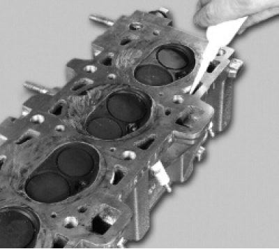
27. Pour kerosene into the water jacket channels. If the kerosene level drops, the head has cracks and needs to be replaced. After checking, do not forget to remove the cardboard gasket.
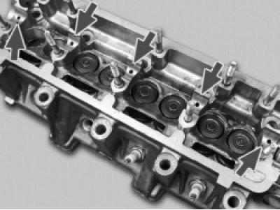
28. Check the condition of the bearing surfaces under the shaft journals on the cylinder head and bearing housings. If at least one of them shows signs of wear, scoring or deep scratches, replace the head and bearing housings.
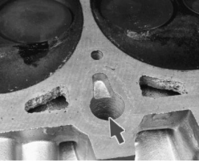
29. Flush the oil channels. To do this, plug the vertical oil channel on the combustion chamber side (the channel is located between the 3rd and 4th cylinders)…
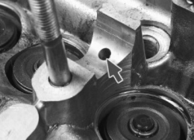
30. …pour gasoline into the oil channels in all camshaft bearings and leave for 15-20 minutes. Pour out the gasoline, remove the plug and finally flush the channels with gasoline using a bulb syringe.
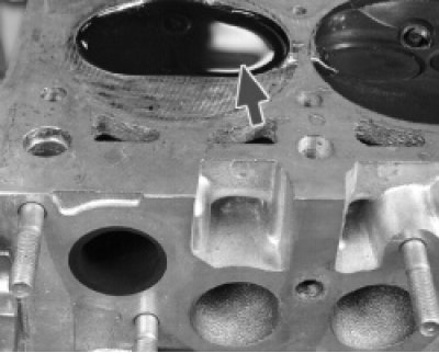
31. To check the tightness of the valves, pour kerosene into the combustion chambers. If kerosene does not leak out of the combustion chambers within 3 minutes, the valves are tight. Otherwise, grind them (see "Lapping valves") or replace the valves.
Note: The valve drive consists of the following parts:
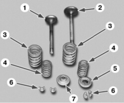
1, 2 — valves; 3 - outer spring; 4 - internal spring; 5 - top plate; 6 - cracker; 7 — lower plate. To replace or grind the valves, all parts must be removed from the cylinder head.

32. Place a suitable support, such as bearing 1, under the valve to be removed.
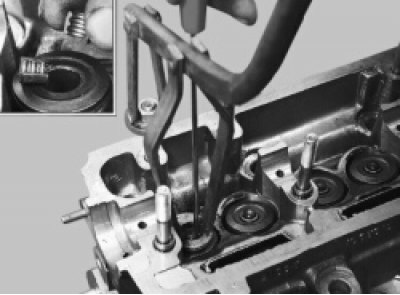
33. Install the valve spring compressor and compress the valve springs. Remove the two crackers with a screwdriver or tweezers.
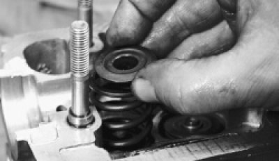
34. Remove the upper spring plate, outer and inner valve springs. Similarly, remove the crackers, plates and springs of the remaining valves.
(The source is on the website: «vazbook.ru»)
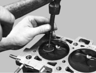
35. Mark the valves with cylinder numbers, for example by punching.
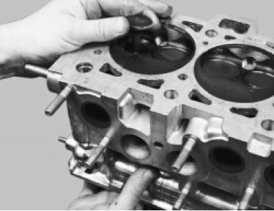
36. Push the valves from below and remove them from the cylinder head.
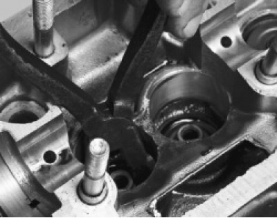
37. Remove the oil seals using a tool or pliers (see "Replacing valve stem seals").
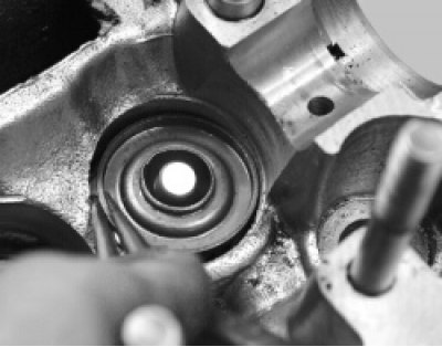
38. Remove the lower valve spring plates.
39. Clean carbon deposits from the valves with a suitable tool (for example, with a metal brush). Then carefully inspect the valves.
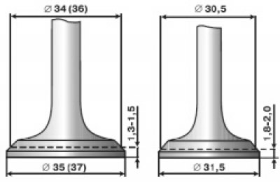
4.8. Valve Plate Dimensions
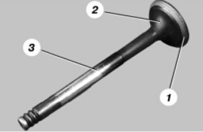
40. Replace valves with the following defects: deep scratches and grooves on the working chamfer 1, cracks, deformation of the stem 3 of the valve, warping of the plate 2 of the valve, traces of burnout. Shallow scratches and grooves on the working chamfer can be removed by grinding the valves (see "Lapping valves").
41. In a specialized workshop, the working chamfer of valves with damage that cannot be removed by grinding can be ground on a special machine. When grinding, it is necessary to maintain the dimensions indicated in Fig. 4.8.
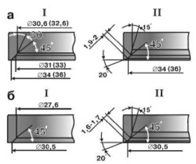
4.9. Dimensions of valve seats: a — inlet valve seat; b - exhaust valve seat; I - new village; II - saddle after repair
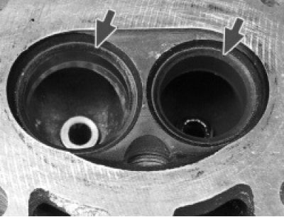
42. Check the condition of the valve seats. There should be no signs of wear, cavities, corrosion, etc. on the working chamfers of the seats. The valve seats can be replaced in a specialized workshop.
Minor damage (minor scratches) can be removed by grinding the valves (see "Lapping valves").
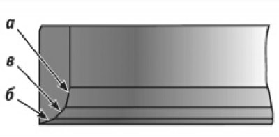
4.10. Valve seat chamfer machining areas
43. More significant defects of valve seats are eliminated by grinding. When grinding, maintain the dimensions indicated in Fig. 4.9. It is recommended to grind the seats in a specialized workshop.
44. If you have metalworking skills, you can do this manually using a set of special cutters.
First, chamfer a (Fig. 4.10) is processed at an angle of 15°, then chamfer b at an angle of 20° and chamfer c at an angle of 45°. After grinding, it is necessary to lap the valves (see "Lapping valves").
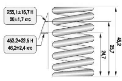
4.11. External spring test parameters
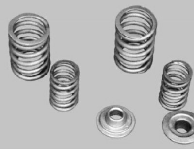
45. Check the condition of the outer and inner valve springs. Replace any springs that are bent, broken or cracked.
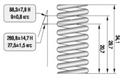
46. To check the elasticity of the outer spring, measure its height in a free state (Fig. 4.11), and then under two different loads. If the spring does not meet the required parameters, replace it.
47. To check the elasticity of the inner spring, measure its height in a free state and then under two different loads (Fig. 4.12). If the spring does not meet the required parameters, replace it.
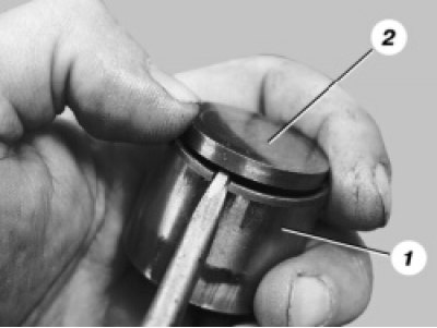
48. Inspect the valve tappets. If there are nicks, scratches, etc. on the working surface 1 of the tappet, replace the tappets. There should be no nicks, dents, scratches, or traces of stepped or uneven wear of the metal on the working surfaces of the adjusting washers 2. If such defects are present, the washers should be replaced. Concentric traces of running-in with the camshaft cams are allowed on the washers.
49. Check the clearances between the guide bushings and the valves.
Clearances between valve and guide bushing, mm:
- nominal clearance for intake valves …0.022-0.055
- nominal clearance for exhaust valves …0.029-0.062
- maximum permissible clearance for intake and exhaust valves...0.3
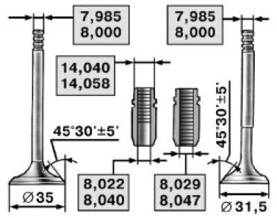
4.13. Dimensions of valves and their guide bushings
The clearance is calculated as the difference between the diameter of the hole in the sleeve and the diameter of the valve stem (Fig. 4.13).
It is recommended that the gap be checked in a specialized workshop, since a special tool (a bore gauge) is needed to measure the diameter of the bushings.
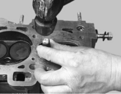
50. If the clearance has not reached the maximum permissible value, you can try to eliminate it by replacing the valve. If this fails or the clearance exceeds the maximum permissible value, replace the guide bushing. To do this, press out the defective bushing from the combustion chamber side using a special mandrel.
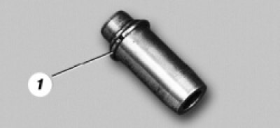
51. Bushings with retaining rings 1 are supplied as spare parts. The outer diameter of the bushing is increased, the diameter of the hole for the valve is reduced.
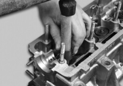
52. After lubricating the bushing with engine oil, insert it into a special mandrel and press it in from the camshaft side until the retaining ring stops against the cylinder head. Ream the hole in the bushing using a reamer to 8.022-8.040 mm for intake valves and to 8.029-8.047 mm for exhaust valves.
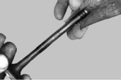
53. If an old valve is being installed, remove any burrs from the grooves under the crackers. After this, it is necessary to grind the valve to the seat [see. "Lapping valves" in the subsection "Cylinder head (repair)"].
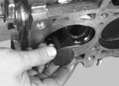
54. Install the valves in the cylinder head in accordance with the previously made markings, having first lubricated their stems with engine oil.
55. Install the lower valve spring retainers.
56. Install the oil seals (see "Replacing valve stem seals").
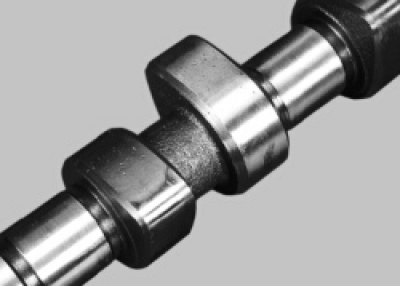
57. Replace the camshaft if its journals and cams show signs of wear, scoring, and deep scratches. In workshops equipped with special tools and devices, you can check the radial runout of the camshaft journals (it should not exceed 0.02 mm) and the gap between the bearing holes and the camshaft journals, which should not exceed 0.2 mm (clearance for new parts 0.069-0.11 mm).
58. Install the camshaft and bearing housings (see "Replacing valve stem seals" in the subsection "Replacing engine sealing parts").
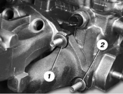
59. Install the gaskets, exhaust manifold and intake pipe. Note that under the nuts (4 pcs.) that simultaneously secure the intake pipe and exhaust manifold, washers 1 of a larger diameter are installed than washers 2 under the other nuts…
60. …and washers are not installed under the receiver bracket mounting nuts.
61. Install the head on the cylinder block (see "Replacing the cylinder head gasket" in the subsection "Replacing engine sealing components"), check the valve clearances and adjust them if necessary (see "Adjusting valve clearances").