




1. Disconnect the wires from the "+" and "–" terminals and remove the battery.
2. Remove the hood (see "Removal and installation the hood").
3. Drain the coolant from the engine cooling system (see "Replacing the coolant").
4. Remove the air filter with the intake pipe hose (see "Removal and installation the air filter" in the subsection "Power supply system").
5. Loosen the mounting bolts and remove the engine crankcase guard.
6. Remove the exhaust pipe (see "Replacing the inlet pipe" in the subsection "Exhaust system").
7. Drain the oil from the engine crankcase (see "Changing engine oil and oil filter").
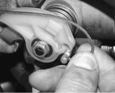
8. Turn the throttle drive sector all the way and disconnect the throttle drive rod from it.
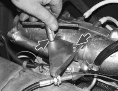
9. Remove the two bolts securing the throttle linkage bracket. Move the bracket aside without disconnecting the linkage from it, so that it does not interfere with engine removal.
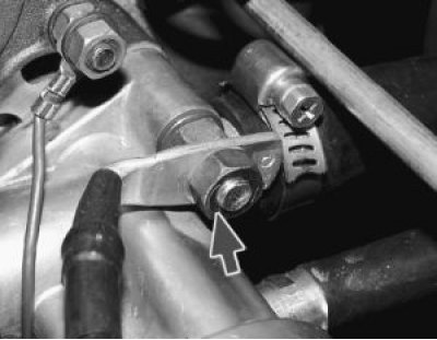
10. Unscrew the fastening nut and remove the engine ground wire tip from the stud on the clutch housing.
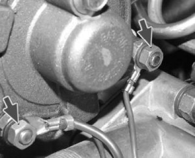
11. Unscrew the two fastening nuts and remove the ends of the ground wires from the fastening studs of the rear cover of the cylinder head.
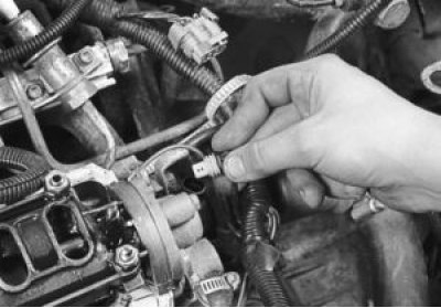
12. Disconnect the wiring harness from the coolant temperature sensor by pressing the plastic clamp.
13. Loosen the clamps and disconnect the radiator inlet pipe, the throttle body inlet hose from the outlet pipe, and disconnect the radiator inlet hose from the thermostat.
14. Disconnect the heater radiator outlet hose and the cooling system filler hose from the water pump inlet pipe (see "Replacing the cylinder head gasket").
15. Disconnect the wire from the coolant temperature gauge sensor (see "Replacing the cylinder head gasket").
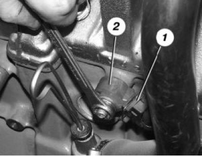
16. Disconnect connector 1 with wires from detonation sensor 2 or remove the sensor by unscrewing its mounting nut and removing the sensor from the stud, leaving it on the wiring harness.
17. Disconnect the wiring harness from the low-voltage terminal of the ignition module by pressing the plastic latch.
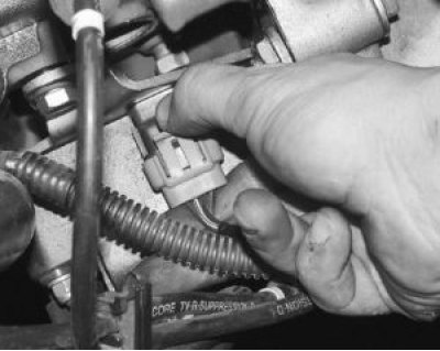
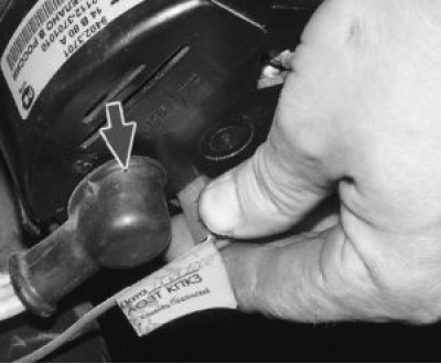
18. Disconnect the connector with wires from the "D" terminal of the generator. After moving the rubber boot, unscrew the nut and disconnect the wires from the contact bolt (terminal "B+") of the generator.
19. Disconnect the wire from the low oil pressure warning light sensor.
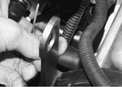
20. Loosen the clamp and disconnect the brake booster hose from the receiver fitting.
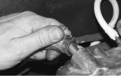
21. Disconnect the wiring harness connector from the throttle position sensor…
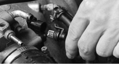
22. ...and from the idle speed controller, pressing the plastic latches.
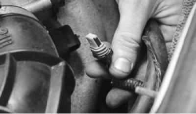
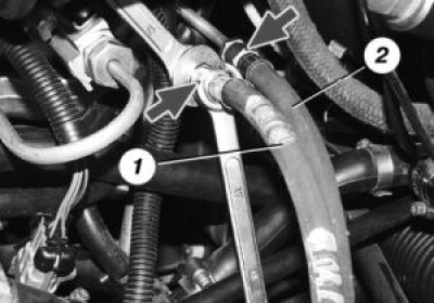
23. Loosen the fastening nuts, holding the hoses from twisting with a second wrench, and disconnect the fuel supply hoses 1 and drain hoses 2 from the fuel pipes (the fuel supply hose is marked with paint).
25. Disconnect the heater outlet hose from the water pump inlet pipe.
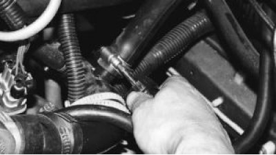
26. Disconnect the injector wiring harness connector by pressing the plastic latch.
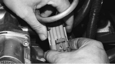
27. Loosen or cut the clamp securing the wire harness to the water pump inlet pipe.
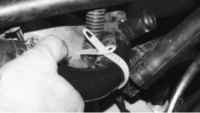
28. From underneath the vehicle, disconnect the wiring harness connector from the 1 oil level sensor in the engine crankcase (next to the oil filter 2).
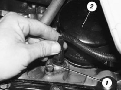
29. Disconnect the wiring harness connector from the crankshaft position sensor.
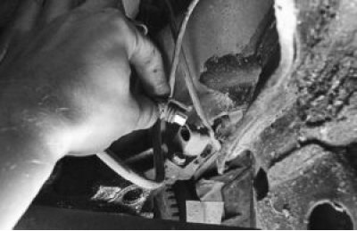
30. Disconnect the wiring harness connector from the vehicle speed sensor.
31. Disconnect the holder with wires from the front camshaft drive belt cover.
32. Remove the wiring harness from under the receiver and thermostat. Check again that all wires and hoses are disconnected from the engine.
33. Loosen the adjusting nuts, disconnect the clutch drive cable from the clutch release fork and remove it from the bracket on the gearbox.
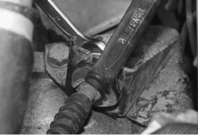
34. Loosen the clamp and disconnect the gear shift drive rod from the joint end.
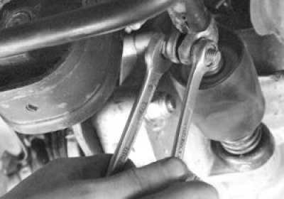
35. Disconnect the wiring harness connector from the reverse light switch on the gearbox.
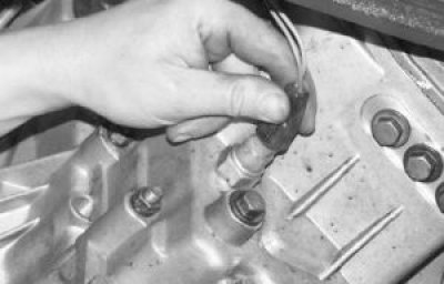
36. Loosen the nuts securing the left and right struts to the suspension arms.
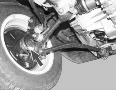
37. Unscrew the three bolts securing the strut bracket to the body and move the left and right struts to a position so that they do not interfere with the removal of the power unit.
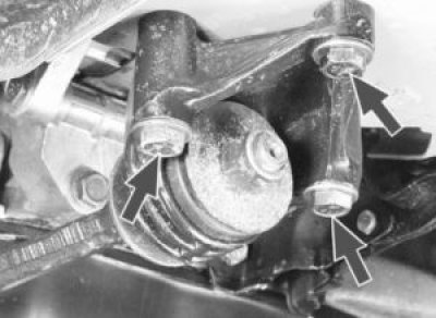
38. Remove the cotter pin from the nut securing the ball joint of the steering rod to the steering arm.
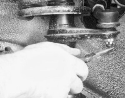
39. Loosen the nut securing the ball joint of the steering rod.
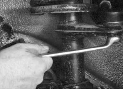
40. Press out the ball joint pin of the steering rod from the steering column pivot arm using a special puller.
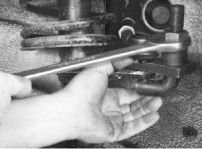
41. Remove the two bolts and disconnect the suspension arm ball joint from the steering knuckle.
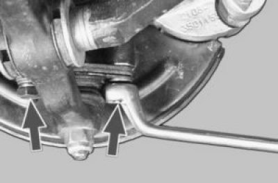
42. Using a pry bar, press the tail of one of the inner joints of the front wheel drive out of the gearbox and move it to the side.
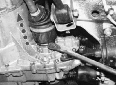
43. Insert a mandrel instead of a hinge (for example, the old inner hinge), so that the axle gear does not turn. After this, disconnect the second drive in the same way as the first.
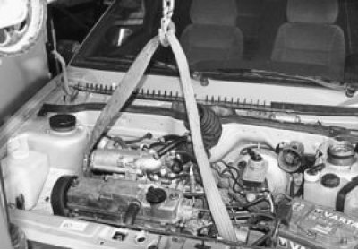
44. Secure the engine to the eyes and tighten the hoist cables.
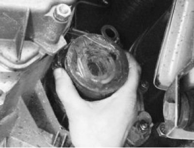
45. Unscrew the two nuts securing the rear support of the power unit to the body.
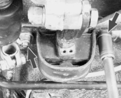
46. Loosen the nut, slightly lift the engine and remove the bolt of the right front support of the power unit.
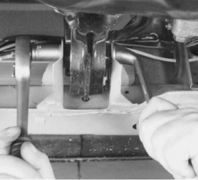
47. Loosen the nut and remove the bolt from the left front support of the power unit.
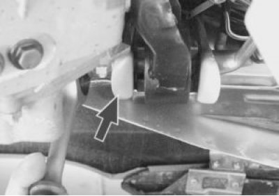
48. Lower the engine onto supports, lift the car and remove the engine from underneath.
Helpful Hint: This section describes how to remove the engine downwards according to the manufacturer's recommendations (as part of a power unit together with a gearbox). This requires lifting mechanisms to raise the front of the car higher. In a garage, it is easier to remove the engine upwards, having first removed the gearbox.