
Cylinder head
Before checking, install the cylinder head on a stand in the form of a metal or wooden frame, remove carbon deposits from the walls of the combustion chambers and from the surface of the exhaust channels with a conventional metal brush or a driven electric drill. Clean and inspect the inlet channels and oil supply channels to the valve drive levers.
If there have been cases of coolant getting into the oil, then the tightness of the cylinder head is checked, for which purpose the plugs included in the kit A.60344 are installed on the head and water is pumped into the head under a pressure of 5 kgf·m. Within 2 minutes, no water leakage from the engine cylinder head should be observed.
You can check the cylinder head with compressed air, for which the parts included in the kit A.60334 are installed on the cylinder head, lowered into a bath of water heated to 60-80°C, and allowed to warm up for 5 minutes. Compressed air is supplied inside the head at a pressure of 1.5–2 kgf/cm2. Within 1-1.5 minutes, no air should escape from the head.
If cracks are found, the cylinder head is replaced.
Valve seats
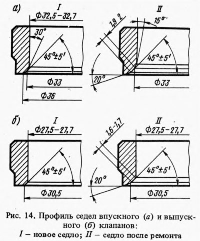
Saddles (pic. 14) should not have on the working chamfers (valve contact area) pitting, corrosion and other damage. Minor damage to the surface of the working chamfers is eliminated by grinding with a grinder or by hand.
For grinding, install the cylinder head on a stand in the metal or wooden frame and insert the A.94059 rod into the valve guide (there are two rods of different diameters: A.94059/1 for inlet valve guides and A.94059/2 for exhaust valve bushings). Carbon deposits and hardening are removed from the chamfers of the seats with A.94031 and A.94092 countersinks for exhaust valve seats and A.94003 and A.94101 countersinks for inlet valve seats. Countersinks are put on the mandrel A.94058 and centered by guide rods A.94059.
After cleaning the chamfers, put the spring A.94059/5 on the rod A.94059, install the conical circle A.94078 for exhaust valve seats or the circle A.94100 for inlet valve seats on the mandrel A.94069, fix the mandrel in a grinding machine and grind the seat, while removing as little metal as possible.
At the moment the wheel touches the seat, the machine must be turned off, otherwise vibration will occur and the chamfer will be incorrect. It is recommended to edit the circle with a diamond more often.
After grinding, the width of the working chamfer is adjusted to the values indicated in fig. 14. To finish the chamfer of the exhaust valve seat, put on the mandrel A.94058 a countersink A.94031 (angle 20°), then put the mandrel with a countersink on the guide rod A.94059 and countersink the seat to ∅ 30.5 mm. Then, with a countersink A.94092, the width of the chamfer is adjusted to 1.6-1.7 mm (see fig. 14b).
To finish the chamfer of the inlet valve seat, put a countersink A.94003 on the mandrel A.94058 and countersink the seat to ∅ 33 mm (see fig. 14a), then put on the mandrel countersink A. 94101 and bring the width of the working chamfer to 1.9-2 mm.
If grinding fails to eliminate damage on the working facet of the seat, then the cylinder head is replaced.
Valves
Before checking the valves, carbon deposits are removed from them with an ordinary brush or on a polishing machine with rotating brushes, after which they check whether the rod is deformed, whether there are cracks on the plate, whether the working chamfer is too worn or damaged. In the presence of deformation of the rod and cracks in the plate, the valve is replaced. If there is slight damage to the working chamfer of the valve, then it is ground on a grinding machine, maintaining a chamfer angle of 45°30'±5', and making sure that the thickness of the cylindrical part of the valve disc after grinding is not less than 0.5 mm and that exhaust valve was not removed layer of hard alloy deposited on the chamfer.
Valve guides
When checking the valve guides, check the gap between them and the valve stems by measuring the diameter of the valve stem and the hole of the guide bush. The gap must correspond to the data in Table. 2, If it is more than acceptable, the valve is replaced. If excessive clearance between the valve guide and valve stem cannot be corrected by valve replacement alone, replace the valve guide. For this operation, use A.60153/R1. The guide bushings are pressed in with the retaining ring put on until the ring stops in the plane of the cylinder head. To replace the two guide bushings of the intake and exhaust valves of the 1st and 4th cylinders, unscrew the two studs securing the camshaft bearing housing, as they interfere with the installation of the mandrel.
After installing the guide bushings, drill holes in them with reamers (A.90310/1 for inlet valve bushings and A.90310/2 for exhaust valve bushings). Then the valve seat is ground and the width of the working chamfer is adjusted to the required dimensions, as indicated above.
Oil deflector caps for guide bushings
The caps are not allowed to peel off the rubber from the reinforcement, cracks and excessive wear of the working edge. When repairing the engine, it is recommended to always replace the oil seals with new ones.
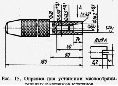
It is recommended to replace damaged valve stem seals with the cylinder head removed so as not to bend the valve stems. To press the caps, use the mandrel 41.7853.4016 (pic. 15).
Valve levers
At the valve levers, the condition of the working surfaces in contact with the valve stem, with the camshaft cam and with the spherical end of the adjusting bolt is checked. If they have scuffs or risks, then the lever is replaced with a new one. If deformation or other damage is found on the bushing of the adjusting bolt or on the bolt itself, then the damaged parts are also replaced.
Valve springs and valve levers
Springs are checked for elasticity and cracks. The elasticity of the valve springs is checked by the length of the spring in the free state (39.2 mm internal and 50 mm external) and under load: 13.9 kgf and (28,1±1,4) kgf for domestic (while the length should be respectively equal to 29.7 and 20 mm); 28,9+2,3-1,5 kgf and (46,1±2,3) kgf for outdoor (while the length is respectively equal to 33.7 and 24 mm).
The data for checking the valve lever springs are as follows. The length of the spring in a free state is 35 mm, and under a load of 5.2-7.5 kgf - 43 mm.
Cylinder head gasket
The surfaces of the gasket must be smooth, free of dents, cracks, swellings and kinks. Detachment of the lining material from the reinforcement is not allowed. There should be no cracks, burnouts and delaminations on the edging of the holes.
Notes
1. Stepped mandrel with a diameter and length of 12.5 and 58 mm, respectively. Centering shank diameter 7.75 mm.