
- key "at 13"
- mandrel for pressing caps
- valve spring compressor
- cap removal tool
- mandrels for pressing and pressing guide bushings
- tweezers
- goatee
- hammer
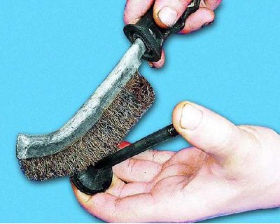
- scraper
Remove the head from the cylinder block (see subsection 10.4.1.) and clean it up.
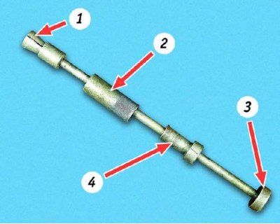
Cap remover: 1 - collet; 2 - bushing; 3 - handle; 4 - striker
With increased clearance in the valve actuator, a characteristic knock appears, usually at regular intervals (its frequency is less than any other knock in the engine). If the adjustment of the clearances in the valve drive did not give positive results, check the condition of the camshaft and bearing surfaces under the camshaft journals.
In workshops equipped with special tools and fixtures, it is possible to check the radial runout of the middle camshaft journal, which should not exceed 0.02 mm, and the gap between the bearing holes and the camshaft journals, which should not exceed 0.2 mm (clearance for new parts is 0.069 - 0.11 mm).
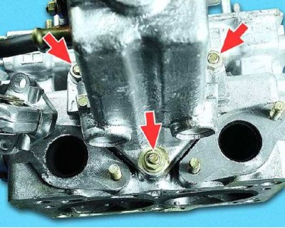
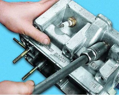
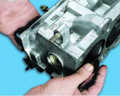
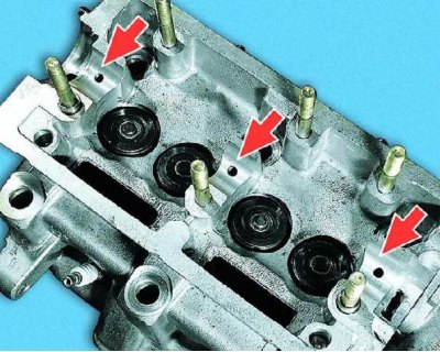
1. Remove the three nuts securing the intake pipe to the block head.
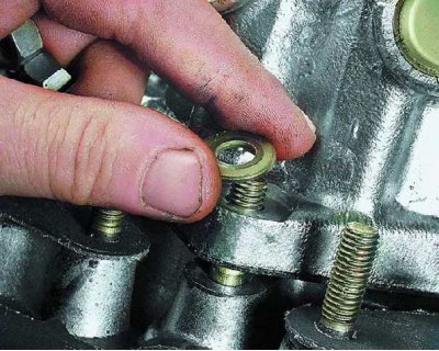
2. Please note: there are flat washers under the nuts.
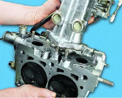
3. Remove the intake pipe from the block head studs.
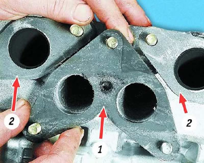
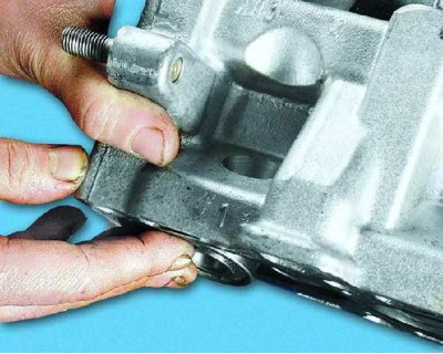
4. Remove from head hairpins a lining 1 inlet pipe and two linings 2 of a reception pipe of the muffler.
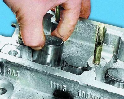
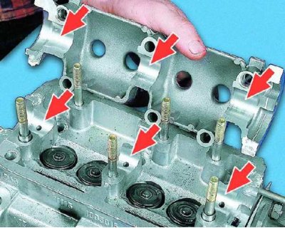
5. Take out pushers of valves with adjusting washers.
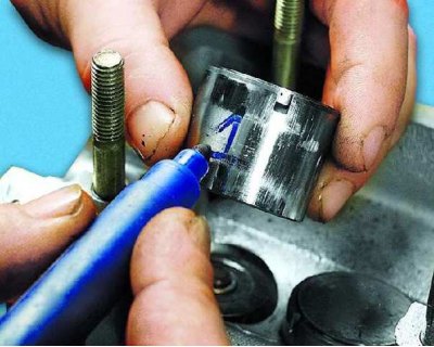
6. Mark the pushers or arrange them in order, so that you can put them in the same place later. Wherein...
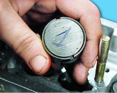
7.... without the need to remove the shims from the pushers, so as not to confuse them.
8. Mark the valves with cylinder numbers, for example, mark them.
9. Remove both spark plugs.
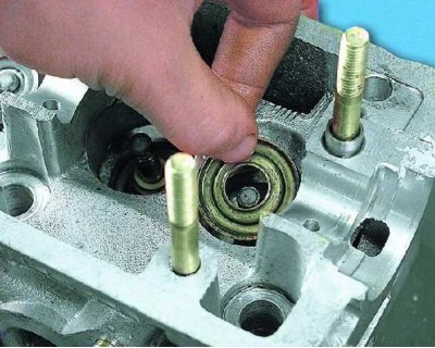
10. Install a suitable stop, such as a bearing, under the valve to be removed.
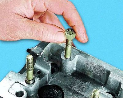
11. Screw a nut onto the stud to secure the valve spring compressor (use a nut without a serrated collar).
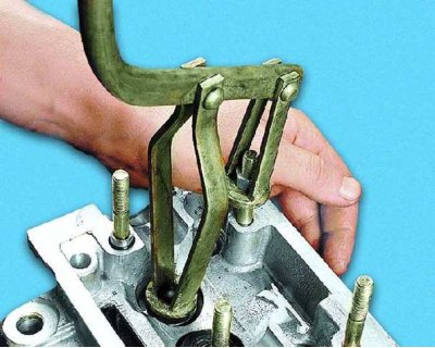
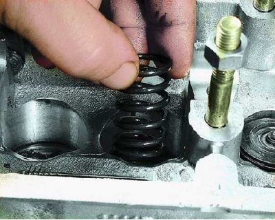
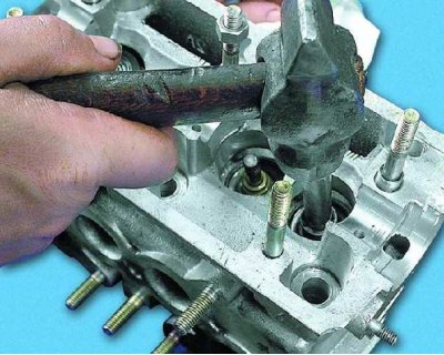
12. Install the valve spring compressor and compress the springs.
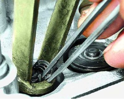
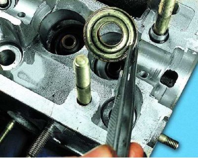
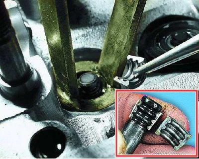
13. Remove two crackers with tweezers. Then remove the fixture.
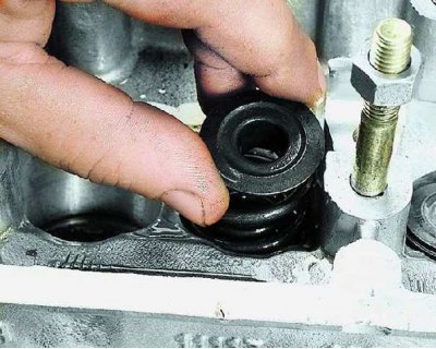
14. Remove the top spring plate...
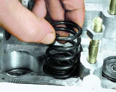
15....outer spring and...
16....an internal valve spring. In the same way, remove the crackers and springs of the remaining valves.
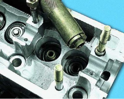
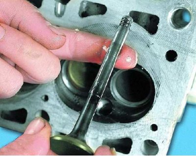
17. Remove the valves from the block head from the side of the combustion chambers.
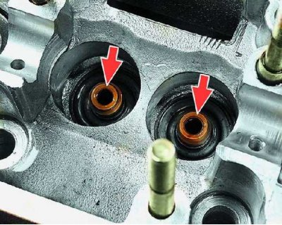
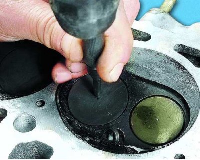
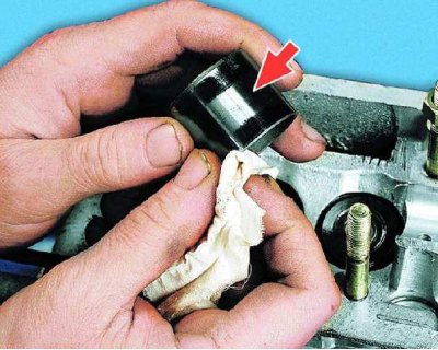
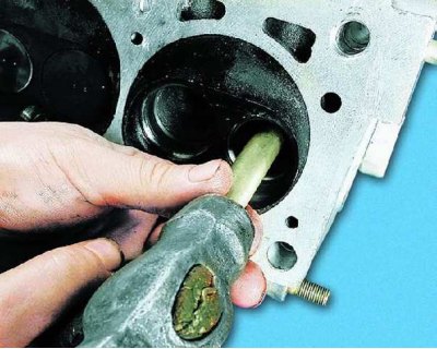
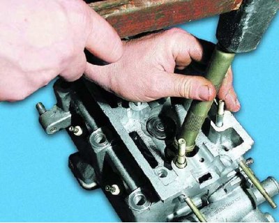
18. Press the valve stem seals off the guide bushings. For this...
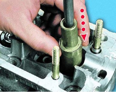
19.... set the tool collet on the cap and hit the tool bush sharply with the striker.
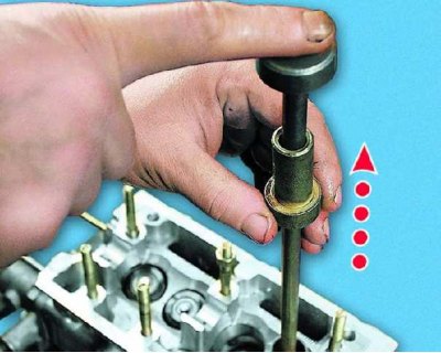
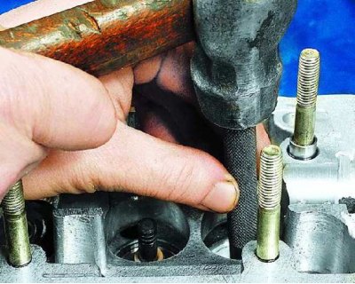
20. Then just as sharply strike the striker on the handle of the device...
21.... thereby pressing the cap from the guide sleeve.
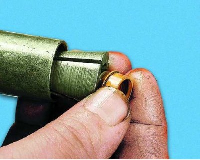
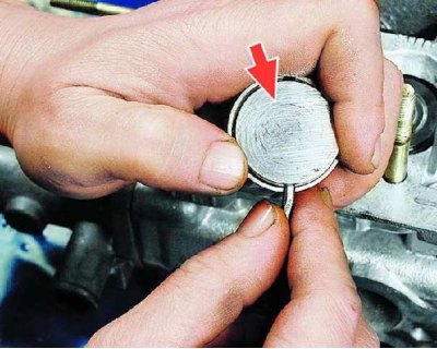
22. Remove the cap from the fixture collet.
23. Remove the lower valve springs.
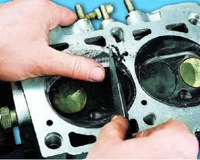
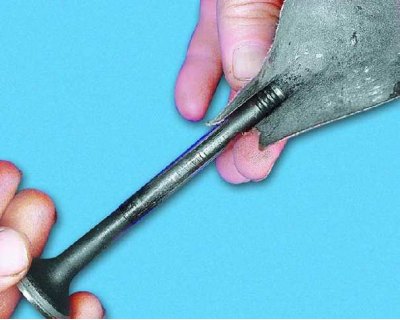
24. Clean carbon deposits from the valves with a suitable metal tool. Then carefully inspect the valves.
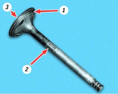
25. Replace valves with the following defects: deep scratches and scratches on the working chamfer 1, cracks, deformations of the stem 2, warping of the plate 3, traces of burnout. Shallow risks and scratches on the working chamfer can be removed by lapping the valves (see subsection 10.5.2.).
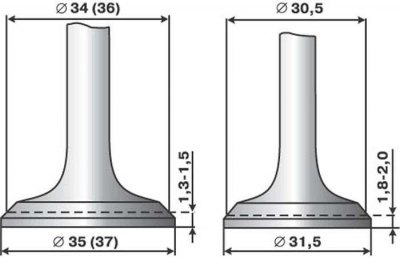
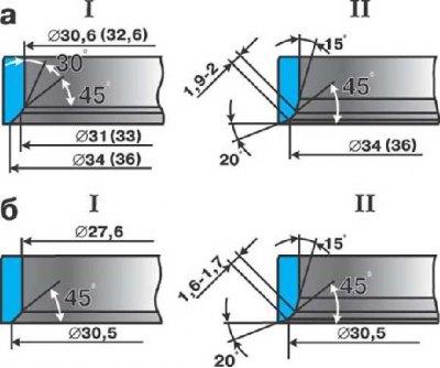
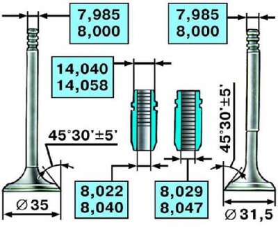
26. In a specialized workshop, the working chamfers of valves with damage that cannot be removed by lapping can be ground on a special machine. When grinding, it is necessary to maintain the dimensions indicated in the figure (in parentheses are the different dimensions for the engine mod. 11113). On the left is the intake valve, on the right is the exhaust valve.
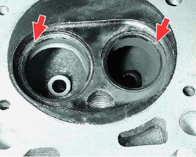
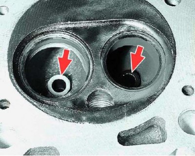
27. Check the condition of the valve seats. Seat faces must be free of wear, pitting, corrosion, etc. The valve seats can be replaced by a specialist workshop. Minor damage (small risks, scratches, etc.) can be removed by lapping valves (see subsection 10.5.2.).
28. More significant defects in valve seats are eliminated by grinding to the dimensions indicated in the figure: a - inlet valve seat; b - exhaust valve seat; I - new seat; II - seat after repair. Saddles are recommended to be ground in a specialized workshop. In parentheses are the different dimensions for the engine mod. 11113.
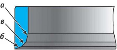
29. Having a locksmith skill, you can eliminate defects manually using a set of special cutters. First, chamfer a is processed at an angle of 15°, then chamfer b at an angle of 20°and chamfer c at an angle of 45°. After processing, it is necessary to grind the valves (see subsection 10.5.2.).
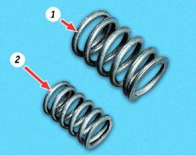
30. Check the condition of the outer 1 and inner 2 valve springs. Replace bent, broken or cracked springs.
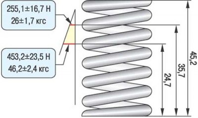
31. To check the elasticity of the outer spring, measure its height in a free state, and then under two different loads. If the spring does not meet the required parameters, replace it.
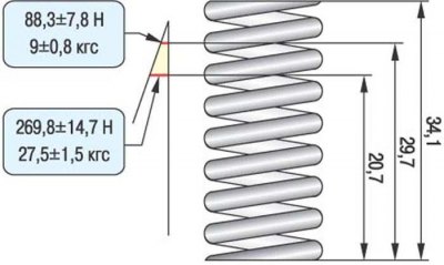
32. In the same way, check the elasticity of the inner spring. If the spring does not meet the required parameters, replace it.
33. Check the valve lifters. If there are scores, scratches, etc. on the working surface of the pusher, replace it.
34. On the working surfaces of the adjusting washers there should be no scoring, nicks, scratches, traces of stepped or uneven wear, metal enveloping. With such defects, the washers must be replaced. Concentric burn-in marks with camshaft cams are allowed on the washers.
35. Have the clearance between the guide bushings and valves checked by a specialist workshop. It is defined as the difference between the bore diameter of the sleeve and the diameter of the valve stem.
36. A special tool is needed to measure the diameter of the bushing hole (caliper). The nominal clearance for intake valves is 0.02-0.05 mm, and for exhaust valves it is 0.03-0.06 mm. The maximum allowable clearance for intake and exhaust valves is 0.3 mm.
37. A gap that has not reached the maximum permissible value can be eliminated by replacing the valve. If you cannot find the valve or the gap exceeds the maximum allowable, replace the guide sleeve. Press out the sleeve from the side of the combustion chamber with a special mandrel.
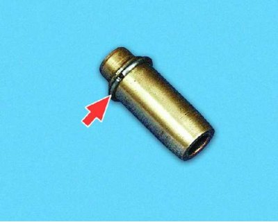
38. Spare parts are supplied with bushings with retaining rings. The bushings have an increased outer diameter and a reduced valve hole diameter.
39. After lubricating the bushing with engine oil, insert it into a special mandrel and press it from the side of the camshaft until the retaining ring stops against the head of the block. After that, expand the hole in the sleeve using a reamer to a diameter of 8.022-8.040 mm for inlet and 8.029-8.047 mm for exhaust valves.
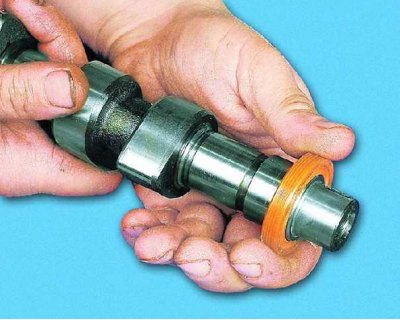
40. Remove the oil seal from the camshaft.
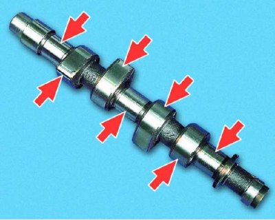
41. Replace the camshaft if its journals and cams show signs of wear, scoring and deep scratches.
42. Replace the block head and bearing housing if they are cracked or the bearing surfaces show signs of wear, scoring, or deep scratches. The bearing housing is machined together with the block head, so they need to be changed together.
43. Clean the combustion chambers from soot. Examine the head. If it has cracks or burn marks in the combustion chambers, replace the camshaft head and bearing housing.
44. Remove burrs and nicks from the mating surface of the block head.
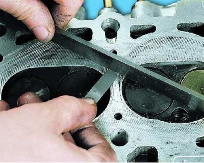
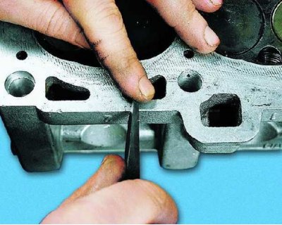
45. Check the flatness of the surface adjacent to the cylinder block. To do this, place the ruler with an edge on the surface of the head in the middle along the axis of the head, and then measure the gap between the plane of the head and the ruler along the diagonals and with a feeler gauge. Replace the head if the gap exceeds 0.1mm.
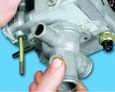
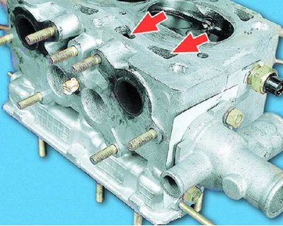
46. To check the tightness of the head, remove the cooling system pipe from the studs by unscrewing the two fastening nuts; plug the hole in the head of the block by installing, for example, a blank gasket made of thick cardboard under the pipe; tighten the nuts and...
47....pour kerosene into the channels of the water jacket. If the kerosene level drops, then there are cracks in the head and it must be replaced. After checking, do not forget to remove the cardboard gasket.
48. Wash the oil channels of the block head with gasoline using a pear or syringe and blow with compressed air.
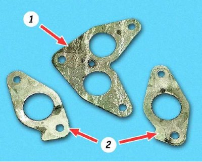
49. Replace damaged gaskets for inlet 1 and outlet 2 muffler pipes.
50. Lap the valve to the seat (see subsection 10.5.2.). If you are installing an old valve, deburr the cracker grooves.
51. Lubricate the valves with engine oil and install them in the head in accordance with the previously made markings.
52. Install the lower valve springs.
53. Using a mandrel, press in the valve stem seals, after lowering them into the oil (see subsection 10.4.3.).
54. Install the springs and upper spring plate in the reverse order of removal. Install the crackers with the tool so that they fit into the grooves of the valve stem.
55. Hit the ends of the valves with a hammer through the metal rod so that the crackers sit in place. Install the pushrods and intake pipe with gaskets in the reverse order of removal.