
Cylinder head
Thoroughly wash the cylinder head and clean the oil channels. Remove carbon deposits from the combustion chambers and from the surface of the exhaust channels with a metal brush.
Inspect the cylinder head. On the beds under the camshaft journals and in the holes for the valve lifters there should be no scoring or damage. Cracks in any places of the cylinder head are not allowed. If you suspect that coolant has entered the oil, check the tightness of the cylinder head.
To check the tightness, close the holes of the cooling jacket with plugs and pump water under a pressure of 5 kgf / cm2. Within 2 minutes there should be no leakage of water from the cylinder head. You can check the tightness of the cylinder head with compressed air, for which they plug the holes in the cooling jacket with the plugs of tool 67.7871.9510, lower the cylinder head into a bath of water heated to 60-80°C, and let it warm up for 5 minutes. Then compressed air is fed into the head at a pressure of 1.5–2 kgf/cm2. Within 1-1.5 minutes, air etching from the cylinder head should not be observed.
Valve seats
On the working chamfers of saddles (pic. 46) in the contact area with the valves there should be no pitting, corrosion and damage. If there are sagging of metal along the inner diameter of the seat, in the zone of the working edge, then they are removed with cutters A.94092 (for exhaust valve) and A. 94003 (for intake valve), keeping the dimensions ∅ 27.6 and ∅ 31 mm. The cutters are put on the spindle A.94058 and centered with guide rods from the set A.94059.
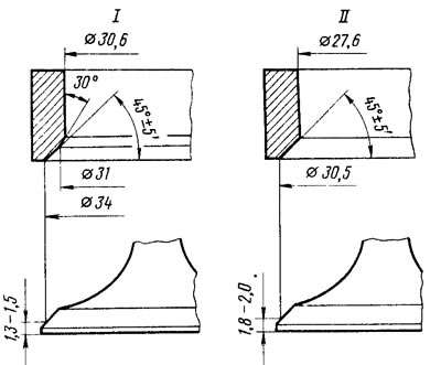
Pic. 46. Profile of seats and intake heads (I) and graduation (II) valves
They check the tightness of the valves, for which they carefully clean the seats and valves, install valves with springs in the cylinder head and pour kerosene into the inlet and outlet channels of the cylinder head. When holding for 3 minutes, no leakage of kerosene through the valves should be observed.
In case of valve leaks, grind them to the seats using lapping paste and a mandrel with a rubber suction cup or a special drill, turning the valve alternately in both directions. During lapping under the valve, it is recommended to install a release spring with low elasticity.
After lapping, the seats and valves are thoroughly washed from the lapping paste and blown with compressed air.
Valves
Remove carbon deposits from valves. Check if the rod is deformed (non-straightness of the rod is not more than 0.015 mm) and there are no cracks on the valve head. The damaged valve is replaced.
Check the condition of the working chamfer of the valve. In case of minor damage, it can be sanded, maintaining a chamfer angle of 45°30'±5'. In this case, the distances from the lower plane of the valve head to the base diameters (∅ 34 and ∅ 30.5 mm) should be as shown in Fig. 46.
Valve guides. Check the clearance between the valve guides and the valve stems by measuring the valve stem diameter and the valve stem bore. The gap size must correspond to the data tab. 1. If the clearance is greater than the allowable value, replace the valve. If excessive clearance cannot be corrected by valve replacement alone, replace the guide bushing as well. For this operation, use the mandrel A.60153 / R *, pressing the bushings with the retaining ring on until it stops against the body of the cylinder head.
* Stepped mandrel with a diameter and length of 12.5 and 58 mm, respectively. Centering shank diameter 7.75 mm.
As spare parts, guide bushings are supplied with an outer diameter increased by 0.02 mm and with an allowance for the inner diameter. Therefore, after pressing, drill holes in the guide bushings with reamers (A.90310/1 for inlet valve bushings and A.90310/2 for exhaust).
Then check the tightness of the valves and, if necessary, grind the valves to the seats.
Oil deflector caps for guide bushings
At oil seals, delamination of rubber from fittings, cracks and excessive wear of the working edge are not allowed. When repairing the engine, it is recommended to always replace the oil seals with new ones.
It is necessary to replace damaged caps on the removed cylinder head so as not to bend the valve stems. To press the caps, use the mandrel 41.7853.4016 (see fig. 40).
Springs and pushrods
Springs are checked for elasticity and cracks. The elasticity of the valve springs is checked by the length of the spring in the free state (44.7 mm external and 35.2 mm internal) and under load: 26+1,9-1,5 and 47.4+2,5-2,3 kgf for outdoor (while the length should be respectively 33.7 and 24.7 mm); 11+1,1-0,7 and 29+1,6-1,4 kgf for domestic (while the length is respectively 29.7 and 20.7 mm).
Check the condition of the working surface of the pusher. It should not have nicks or scratches. In case of damage, the pusher is replaced.
Adjusting washers, cylinder head bolts
The working surfaces of the washers must be smooth, without nicks, scratches and scuffs. They should not have stepped or one-sided wear, metal rubbing. Concentric run-in marks with camshaft cams are allowed.
With repeated use of the cylinder head bolts, they are pulled out. Therefore, it is checked whether the length of the bolt exceeds 135.5 mm (without taking into account the height of the bolt head), and if it is more, then replace the bolt with a new one.