




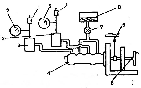
Fig. 6-12. Master cylinder tightness test diagram: 1 - valve for bleeding the stand; 2 - pressure gauge; 3 - absorption cylinder; 4 - master cylinder; 5 - flywheel, 6 - pushrod offset indicator. 7 - tap; 8 - vessel
Open valves 1 to bleed the stand and, moving the master cylinder pistons several times to the full length of their stroke, bleed the system. Then close valves 1. Rotating flywheel 5, slowly move the master cylinder pistons until the pressure monitored by pressure gauges 2 reaches 12.5 MPa (125 kgf/cm²). In this position, lock the master cylinder pushrod. The specified pressure should remain constant for at least 5 sec.
In case of fluid leakage or decrease in the set pressure within 5 seconds, replace the cylinder piston seals.