




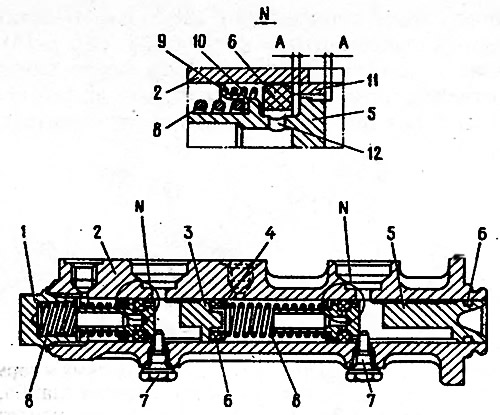
Fig. 6-10. Master cylinder of the hydraulic brake drive: 1 - cork; 2 - cylinder body; 3 - front brake actuator piston; 4 - washer; 5 - piston for rear brake drive and additional front brake drive; 6 - sealing ring; 7 - locking screws; 8 - piston return springs; 9 - spring plate; 10 - seal pressure spring; 11 - spacer ring. 12 - inlet hole; A - compensation hole (gaps between seal 6, ring 11 and piston 5).
[The information is published on the website VazBook]