




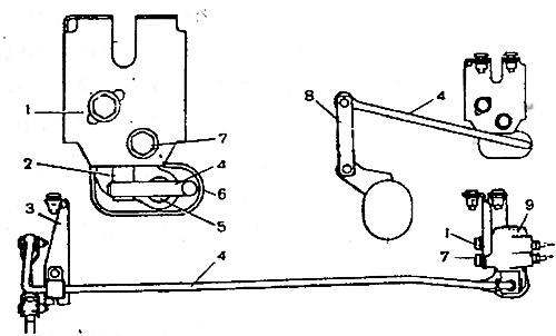
Fig. 6-6. Diagram of installation of the rear brake pressure regulator and its adjustment: 1, 7 - regulator mounting bolts; 2 - piston; 3 - support sleeve bracket; 4 - pressure regulator drive lever; 5 - axis; 6 - protective cap; 8 - traction; 9 - pressure regulator; X = 150±5 mm.
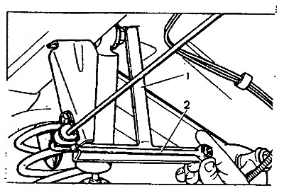
Fig. 6-7. Installing the 67.7820.9519 tool to adjust the position of the rear brake pressure regulator: 1 - fixture 67.7820.9519; 2 - pressure regulator drive lever
Lift the protective rubber cap 6 (Fig. 6-6) and, by turning the pressure regulator on the bolts, achieve light contact of the lever with piston 2.
Holding the regulator in this position, tighten bolts 1 and 7 until they stop, then coat axle 5 and the protruding part of piston 2 with a thin layer of DT-1 grease. Place 5-6 g of the same grease in rubber cap 6 and install it in place.
Remove tool 67.7820.9519 and connect the end of the lever to rod 8.