




Open large image in new tab »
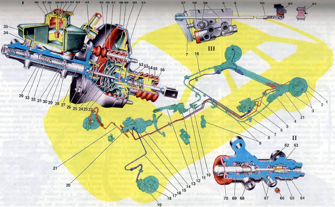
Figure 28. Brake drive: 1. Rear wheel brake shield; 2. Rear brake wheel cylinder; 3. Rear brake pads; 4. Rear brake hose; 5. Elastic lever of pressure regulator drive; 6. Pressure regulator mounting bracket; 7. Pressure regulator drive lever; 8. Rear parking brake cable assembly; 9. Pipeline fastening bracket; 10. Cable equalizer; 11. Parking brake rod; 12. Parking brake lever bracket; 13. Parking brake lever; 14. Vacuum booster; 15. Master cylinder reservoir; 16. Pipeline of the circuit "left front - right rear brakes"; 17. Front wheel brake disc; 18. Caliper assembly with wheel cylinder and pad guide; 19. Front brake hose; 20. Master cylinder of the brake hydraulic drive; 21. Pipeline of the circuit "right front - left rear brakes"; 22. Diaphragm return spring; 23. Rod; 24. Amplifier housing cup; 25. Rod seal; 26. Adjusting bolt; 27. Piston of the drive circuit "left front - right rear brakes"; 28. Spacer ring; 29. High pressure sealing ring; 30. Sealing ring pressure spring; 31. Spring plate; 32. Piston return spring; 33. Thrust washer; 34. Connecting sleeve; 35. Master cylinder reservoir housing; 36. Tank lid; 37. Reflector; 38. Sensor housing; 39. Protective cap. 40. Movable contact; 41. Fixed contact; 42. Pusher; 43. Float; 44 Vacuum valve; 45. Amplifier housing; 46. Sealing cover; 47. Hairpin; 48. Diaphragm; 49. Amplifier housing cover; 50. Valve body; 51. Rod buffer; 52. Piston; 53. Valve; 54. Air filter; 55. Pusher; 56. Valve body protective cover; 57. Lever spring; 58. Pressure regulator drive lever bracket; 59. Pressure regulator mounting bolts; 60. Earring bracket; 61. Earring; 62. Pusher bushing; 63. Valve seat sealing ring; 64. Pressure regulator valve; 65. Valve seat; 66 Plug; 67. Pusher sealing ring; 68. Piston head seal; 69. Pressure regulator piston; 70. Protective cap; I. Master cylinder and vacuum booster; II. Pressure regulator; III. Brake drive diagram.
The hydraulic drive of the service brake system consists of a pedal, a vacuum booster 14, a master cylinder 20 with a reservoir 15, a pressure regulator, wheel cylinders 2 and 18, brake mechanisms and diagonal circuit pipelines.
The vacuum booster reduces the force on the brake pedal. Between the housing 45 and the cover 49, a diaphragm 48 is clamped, which, together with the valve body 50, divides the cavity of the vacuum booster into two chambers; vacuum A and atmospheric B (see figure 27). Chamber A is connected to the engine intake pipe via a tip and a hose and is isolated from chamber B. Housing 50 (see figure 26) of the valve under the action of spring 22 together with the diaphragm is pressed towards the booster cover. The tail of the housing at the outlet from the cover is sealed and simultaneously protected by the cover 56. The valve housing contains the rod 23 of the master cylinder drive with the support sleeve, piston 52, valve housing sleeve, buffer 51, valve 53, two springs, air filter 54 and pusher 55. The support sleeve is pressed onto the rod 23. It rests through the rubber buffer 51 and the plastic sleeve against the valve housing. An adjusting bolt 26 is screwed into the end hole of the rod. To seal the gap between the flange of the master cylinder and the vacuum booster housing, a rubber ring is installed in the housing seat.
Piston 52 is rigidly connected to the valve body by rolling the disk on the valve end. The ball head of the pusher is compressed in the piston seat. Thus, the piston, valve body and pusher form a single non-separable unit. Rubber valve 53 is pressed against the piston end by a spring. The support sleeve is pressed against the rear end of the valve by another spring. The other end of the spring rests against the support washer of the air filter 54.
The master cylinder of the brake hydraulic drive assembled with the reservoir 15 is secured on the studs of the vacuum booster. In the cavity of the master cylinder, two pistons are located in series, each of which controls its own circuit. Piston 27 is sealed in the cylinder by two rubber rings. The high-pressure sealing ring 29 is pressed by spring 30 to the end of the spacer ring 28. The other end of the spring rests against plate 31. On the other side, return spring 32 rests against the plate. The piston stroke in the cylinder is limited by a lock screw screwed into the cylinder body from below. The end of the screw enters the piston groove. A low-pressure sealing ring is installed in the rear groove of the piston. Piston 27 creates pressure in the "left front - right rear brakes" circuit.
The front floating piston has a similar design, a front part seal and a stroke limitation. Only the rear part is also sealed with a high-pressure ring 29, which is pressed to the end of the piston by a spring 32 through a washer 33. A tank 15 is attached to the main cylinder using two connecting bushings 34, onto the neck of which a cover 36 is screwed, securing the liquid emergency level sensor. Two fixed contacts 41 with terminals are riveted in the sensor housing, onto which the wire tips are put on. A pusher 42 passes through the opening in the base of the tank, on the upper end of which a contact 40 is rigidly attached. A polypropylene float 43 is attached to the lower end of the pusher through a plastic connecting bushing. From above, the sensor contacts are closed with a plastic cap 39.
The pressure regulator is secured with two bolts 59 to the bracket shelf, which in turn is secured to the body floor bracket. The front, longer bolt 59 simultaneously secures the forked bracket 58 of the pressure regulator drive lever 7. To prevent the bracket 58 from turning relative to the bolt 59, its projection enters the groove of the regulator bracket. Due to this groove and the oval holes in the bracket 58 for the fastening bolt 59, the bracket 58 together with the regulator drive lever 7 can be moved relative to the pressure regulator. This adjusts the pressure regulator drive.
A finger is welded to the fork bracket 58, which is a stop for the lever 7. A pin is pressed into the stop hole, relative to which the two-arm lever 7 rotates, in the upper hole of which an axis is located, through the hole of which the end of the elastic lever 5 of the regulator drive passes. The axis of the lever and the elastic lever are locked by a single lock. The other end of the elastic lever 5 is pivotally connected to the earring 61, which swings on the pin of the bracket of the suspension arm.
A plug is screwed into the regulator body on one side, and a bushing is installed on the other side, fixed in the body by a retaining ring. Piston 69 is installed in the bushing. At the outlet from the cylinder, it is sealed by a protective cover 70. The piston head enters the bushing of the regulator body with a gap. The spring presses the sealing rings 67 and 68 to the ends of the bushings through the washers. A rubber-metal valve is installed in the regulator plug, pressed to the seat 65 by the spring. The tightness of the seat fit in the plug is ensured by the sealing ring 63. The valve seat is rolled into the regulator plug. The protruding part of the valve 64 rests against the pusher. It is installed in the bushing 62 and is sealed together with it by two rubber rings 67. The spring through the plate presses the pusher bushing with the sealing rings to the washer, which is held on the pusher by a retaining ring.
(Information copied from the portal VAZbook.ru)
The pressure regulator has four chambers, two of which are connected to the main brake cylinder, and the other two to the wheel cylinders of the rear wheel brake mechanisms.
The mechanical drive of the handbrake consists of a lever 13 with a bracket 12, an adjusting rod 11, a cable equalizer 10, two rear cables 8 and levers 38 (see figure 25) manual brake pad drive.
Lever 13 (see figure 26) is mounted on bracket 12 together with the toothed sector. This unit is non-separable, it is attached to the floor of the body. In engagement with the toothed sector is a latch, which is controlled through the rod by the lever button. All these parts are assembled in the cavity of lever 13. Lever 13 of the parking brake is pivotally connected with the rod 11 by a pin. At the other end of the rod, the equalizer 10 of the cables is fastened with an adjusting nut with a thrust washer. The position of the nut on the rod is fixed with a lock nut. The front ends of the rear cables are put on both ends of the equalizer. The rear ends of the cables are connected to the levers of the manual drive of the brake shoes of the rear wheel (see figure 25).