




Contents: Disassembling the generator ↓ Generator assembly ↓ Replacing the brush holder ↓ Replacing the rotor bearing on the…↓
Disassembling the generator
After removing the nuts from the extension 21 (Fig. 7-9) of the contact bolt and unscrewing the fastening screws, remove the protective cover 19 with the hose. Disconnect the wire bundle 22.
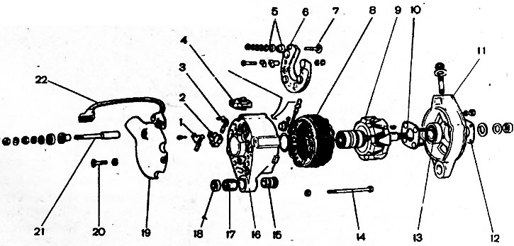
Fig. 7-9. Generator parts: 1 - "negative" brush; 2 - brush holder; 3 - "positive" brush; 4 - neutral wire plug socket; 5 - insulating bushings; 6 - rectifier block; 7 - contact bolt; 8 - stator; 9 - rotor; 10 - inner bearing mounting washer; 11 - drive side cover; 12 - outer bearing mounting washer; 13 - rotor bearing; 14 - tension bolt; 15 - pressure sleeve; 16 - cover from the contact ring side; 17 - buffer bushing; 18 - bushing; 19 - protective cover; 20 - casing mounting screw; 21 - Contact bolt extension; 22 - bundle of wires
Loosen the screws and remove the brush holder 2 with the brushes.
Loosen the nuts of the tie bolts 14 and remove the generator cover 11 together with the rotor.
Clamp the rotor in a vice, unscrew the pulley nut and remove the pulley from the rotor shaft using puller 02.7823.9504. Remove the woodruff key from the groove on the shaft and remove cover 11.
Loosen the nuts of the screws connecting the valve tips to the stator winding terminals, remove the neutral wire plug from block 4 and remove stator 8 from generator cover 16.
Unscrew the nut of the contact bolt 7 and remove the rectifier block 6.
Generator assembly
The generator is assembled in the reverse order of disassembly.
The misalignment of the holes in the generator cover legs should be no more than 0.4 mm. Therefore, during assembly, it is necessary to insert a special gauge into these holes.
[The original is posted on Internet resource VAZBOOK]
The conical spring washer of the pulley must be in contact with the nut with the convex side. Tighten the pulley nut to a torque of 38.2-61.7 N·m (3.9-6.3 kgf·m).
Replacing the brush holder
If the brushes are worn out and protrude from the brush holder by less than 5 mm, replace the brush holder with brushes.
Before installing the brush holder, blow out any carbon dust from the installation area and wipe off any oil mixed with carbon dust.
Replacing the rotor bearing on the drive side
To remove a faulty bearing from the cover, unscrew the nuts of the screws that tighten the bearing mounting washers, remove the washers with the screws and press out the bearing using a hand press. If the nuts do not unscrew (the ends of the screws are pierced), then cut off the ends of the screws.
A new bearing can be installed in the generator cover only if the bearing hole is not deformed and its diameter is no more than 42 mm. If the hole has a larger diameter or is deformed, replace the cover with a new one.
The bearing is pressed into the cover using a press and then clamped between two washers, tightened with screws and nuts. After tightening the nuts, the ends of the screws are punched out.