




Data for verification and adjustment
- Adjustable voltage at regulator and ambient temperature of 50±3°C, V:
- at the second stage - 14.2±0.3
- at the first stage lower than at the second, no more than - 0.7
- Resistance between plug "15" and "ground", Ohm - 27.7±2
- Resistance between plug "15" and plug "67" with open contacts, Ohm - 5.65±0.3
- Air gap between anchor and core, mm — 1.4±0.07
- Distance between contacts of the 2nd stage, mm — 0.45±0.1
The regulator is tested and adjusted on a stand that has a generator, a battery, a thermostat and an electric motor capable of changing the rotation frequency in a wide range. The regulator with a closed cover is installed on the stand with the plugs down.
The electrical connection diagram of the stand is shown in Fig. 7-12. Pay special attention to the reliability of the connections so that their resistance does not exceed the values given in Table 7-4.
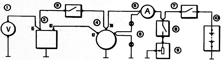
Fig. 7-12. Circuit diagram for testing the voltage regulator on the bench: 1 - voltmeter with a scale of 15 V, accuracy class not lower than 0.5; 2 - voltage regulator; 3 - main switch; 4 - generator; 5 - ammeter with scale up to 50 A; 6 - control lamps 3 W, 12 V; 7 - battery switch, 8 - rheostat switch; 9 - rheostat 5-30 A, 15 V; 10 - battery
Table 7-4. Maximum ohmic resistance value of connections
| Connections | Resistance, Ohm |
| "30" of the generator is the "plus" of the battery | 0.005 |
| "Ground" of the generator - "minus" of the battery | 0.001 |
| "30" generator - "15" regulator | 0.02 |
| "67" generator - "67" regulator | 0.02 |
| "Generator ground" - "Ground" of the regulator | 0.02 |
It is necessary that the wires from switch 3 are connected directly to the "30" terminal of the generator and the "15" plug of the regulator, and the "ground" of the regulator is connected directly to the "ground" of the generator. All connecting wires should be as short as possible. If tray wiring is used (the wires are located in tubes or trays), then the trays must be made of non-magnetic material.
When performing control tests on the bench, do not allow the regulator to operate with the battery disconnected, as this may damage the regulator contacts.
Light bulbs 6 monitor the generator's serviceability and must have the same glow when it is running.
Before testing, warm up the regulator in a thermostat for 5-18 minutes at 50±3°C, supplying the regulator winding with current at a voltage of 12-13 V. The voltage is set by rheostat 9 with switches 3, 7, 8 on and the generator not running.
Immediately after warming up, checking and adjustment is carried out.
Second stage control. Set the generator rotor speed to 5000 min⁻¹. Use rheostat 9 to set the generator load current to 2-12 A. Check the generator voltage, which should be 14.2±0.3 V. If it is different, stop the generator, disconnect the battery, remove the cover from the regulator and, bending bracket 12 (fig. 7-10), loosen up (if high voltage) or increase (if the voltage is low) spring tension 11. Then replace the regulator cover and check the second stage voltage again.
After adjusting the second stage, immediately check the first stage.
First stage control. At a generator rotor speed of 5000 min1, use rheostat 9 (Fig. 7-12) to set the load current to 25-35 A. In this case, the voltage value should be no more than 0.7 V lower than the value obtained when adjusting the second stage.
Note: When checking both the first and second stages, make sure that the adjusted voltage is stable, i.e. does not fluctuate sharply.
If the voltage does not fit within these limits, then stop the generator, disconnect the battery, remove the regulator cover, loosen nut 6 (fig. 7-10) and move rack 8 by 0.1-0.2 mm.
If the voltage is high, the post moves down, and if it is low, it moves up. At the same time, post 7 moves to maintain a gap of 0.45±0.1 mm between the contacts of the second stage. During this operation, ensure that the axes of the contacts of the first and second stages coincide. The anchor contact should not go beyond the contacts on the posts.
Tighten nut 6, replace the cover, check the regulator again (both the first and second stages), and repeat the operations if necessary.
(The text is copied from the online resource VazBook)
After adjustment, thoroughly clean the regulator cap and install it on the hot regulator to minimize moisture absorption.