




Contents: Checking the generator on the car ↓ Testing the generator on the bench ↓ Checking the generator with an…↓ Checking the rotor excitation winding ↓ Stator check ↓ Checking the rectifier valves ↓
Checking the generator on the car
If the battery charge indicator light is on when the engine is running, then the generator's serviceability can be roughly determined as follows:
- slightly pulling the carburetor air damper control handle, bring the idle speed of the crankshaft to 1000-1500 min⁻¹;
- disconnect the negative terminal wire of the battery for a short time. If the engine stalls, this indicates that the generator is faulty and all consumers are powered by the battery.
Testing the generator on the bench
The test bench allows to determine the generator's serviceability and whether its characteristics correspond to the nominal ones. The generator being tested must have its protective cover 6 (fig. 7-4), the brushes must be well ground to the contact rings of the commutator, and the rings themselves must be clean.
Install the generator on the stand and make connections as shown in Fig. 7-6. Turn on the stand's electric motor, use rheostat 4 to set the generator output voltage to 14 V and bring the rotor speed to 5000 min⁻¹. Let the generator run in this mode for at least 2 minutes, and then measure the output current. For a serviceable generator, it should be at least 44 A.
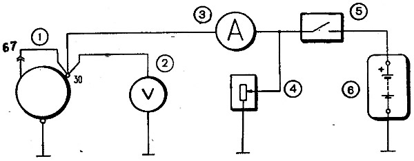
Fig. 7-6. Generator connection diagram on the test bench: 1 - generator, 2 - voltmeter; 3 - ammeter; 4 - rheostat; 5 - switch; 6 - battery
If the measured value of the output current is less, this indicates faults in the stator and rotor windings, damage to the valves or wear of the contact rings and brushes. In this case, a thorough check of the windings and valves is necessary to determine the location of the fault.
If you suspect a fault in the generator rectifier block valves, check the output current on a warmed-up generator. This check allows you to better identify a valve fault by a sharp decrease in output current when the generator temperature rises. To warm up, let the generator run for at least 15 minutes at a rotor speed of 5000 min⁻¹ and a voltage of 14 V at the generator output. Then measure the output current. On a warmed-up generator, it should be at least 42 A.
Checking the generator with an electronic oscilloscope
The oscilloscope allows you to accurately and quickly check the generator's serviceability and determine the nature of the damage based on the shape of the rectified voltage curve.
To check, rotate the generator rotor at a frequency of 1500-2000 min⁻¹, powering the excitation winding from the battery, but disconnect the battery from the "30" terminal.
With serviceable valves and stator winding, the rectified voltage curve has a sawtooth shape with uniform teeth (Fig. 7-7). If you have a break in the stator winding or a break or short circuit in the rectifier valves, the shape is crooked; changes abruptly: the uniformity of the teeth is disrupted and deep depressions appear (fig. 7-7, II and III).
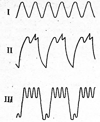
Fig. 7-7. Generator rectified voltage waveform: I - the generator is working; II - the valve is broken; III - break in the valve circuit
Checking the rotor excitation winding
The serviceability of the winding and the reliability of the brushes' contact with the contact rings can be checked on a stand, without disassembling the generator, by measuring the resistance between the "67" plug and the generator's "ground".
If the winding has no short-circuited turns and the brushes are well ground to the contact rings, then the resistance should be 4.4+0,3-0,2 Ohm at a temperature of 20°C. In this case, it is necessary to monitor the reliability of the contact between the rotor rings and the conductors connected to them.
Stator check
The stator is checked separately, after disassembling the generator. The terminals of its winding must be disconnected from the rectifier valves.
First of all, check with an ohmmeter or with a test lamp and a battery to see if there are any breaks in the stator winding and if its turns are shorted to ground.
The insulation of the winding wires must be free of overheating, which occurs when there is a short circuit in the rectifier valves. Replace the stator with such a damaged winding.
Finally, it is necessary to check with a special flaw detector whether there are any short-circuited turns in the stator winding.
Checking the rectifier valves
A working valve only passes current in one direction. A faulty valve may not pass current at all (chain break) or pass current in both directions (short circuit).
If one of the rectifier valves is damaged, the entire rectifier unit must be replaced.
A short circuit of the rectifier valves can be checked without removing the generator from the car, after disconnecting the wires from the battery and the generator. You can check with an ohmmeter, or with a lamp (25-40 W) and a battery, as shown in Fig. 7-8.
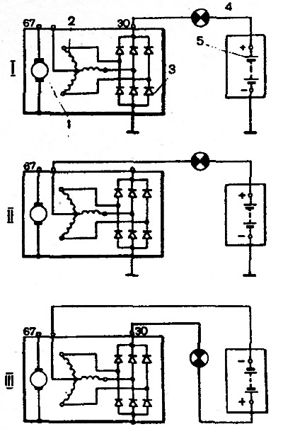
Fig. 7-8. Rectifier valve testing schemes: I - checking both "positive" and "negative" valves simultaneously; II - checking the "negative" valves; III - checking the "positive" valves; 1 - generator rotor; 2 - stator winding; 3 - rectifier valves; 4 - control lamp; 5 - battery
Note. In order to simplify the fastening of the rectifier parts, three valves have a "plus" of the rectified voltage on the body. These are "positive" valves and they are pressed into one plate of the rectifier block. The other three "negative" valves have a "minus" of the rectified voltage on the body and are pressed into another plate of the rectifier block.
First check if there is a short circuit in both the "positive" and "negative" valves. To do this, connect the "plus" of the battery through the lamp to the "30" terminal of the generator, and the "minus" to the generator body (fig. 7-8, I). If the lamp is on, then both the "negative" and "positive" valves are short-circuited.
A short circuit of the "negative" valves can be checked by connecting the "plus" of the battery through a lamp to the plug of the neutral wire of the stator winding, and the "minus" to the generator body (fig. 77-8, II)
If the lamp is on, it means there is a short circuit in one or more "negative" valves.
It should be remembered that in this case the lamp burning may be a consequence of the short circuit of the stator winding turns to the generator housing. However, such a malfunction occurs less frequently than a short circuit of the valves.
To check for a short circuit in the "positive" valves, connect the "plus" of the battery via a lamp to the "30" terminal of the generator, and the "minus" to the plug of the zero point terminal of the stator winding (fig. 7-8, III). The lamp lighting up will indicate a short circuit in one or more "positive" valves.
A break in the valves without disassembling the generator can be detected only indirectly when testing the generator on a bench, by a significant decrease (by 20-30%) in the value of the output current compared to the nominal. If the generator windings are in good condition and there is no short circuit in the valves, then the reason for the decrease in the output current is a break in the valves.