
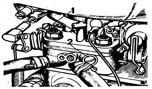
Pic. 2-87. Screws for adjusting the idle speed system of carburetors 2106-1107010: 1 - throttle opening adjustment screw; 2 - mixture adjustment screw
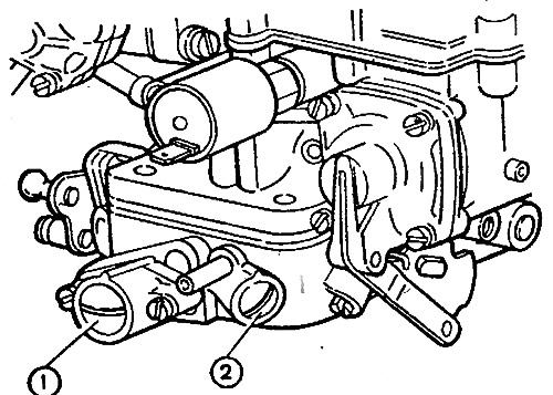
Pic. 2-88. Carburetor idle adjustment screws 2107-1107010-10 and 2107-1107010-20: 1 - mixture quantity screw; 2 - composition screw (quality) mixtures
So that the owner of the car does not violate the factory adjustment, at the carburetor 2107-1107G10-10 and 2107-1107010-20 on screws 1 and 2 (for carburetor 2106-1107010 only for screw 2) restrictive plastic bushings are pressed in, allowing you to turn the screws only half a turn. If it is not possible to adjust the CO content in the exhaust gases with the bushings, then by unscrewing the screws, break the heads of the bushings, unscrew the screws, remove the bushings from them and screw the screws back into the carburetor
Note. The blue bushing is installed at the factory, and red at the service stations.
Idle speed adjustment is carried out on a warm engine (coolant temperature 90-95°C or oil 75-90°C) with adjusted gaps in the gas distribution mechanism and with a correctly set ignition timing.
For carburetors 2106-1107010, adjust in the following order:
- screw 1 (pic. 2-87) set the crankshaft speed on the stand tachometer within 720-800 min-1;
- use screw 2 to achieve the concentration of CO * in the exhaust gases within 1.5-2.5% of the given throttle position;
- screw 1 restore the crankshaft speed to 720-800 min-1;
- if necessary, use screw 2 to restore the CO concentration to 1.5-2.5%;
- press on the screw 1 restrictive plastic sleeve, as shown in fig. 2-89, in.
For carburetors 2107-1107010-10 and 2107-1107010-20, adjust in the following order:
- screw 1 (pic. 2-88) set the crankshaft speed to the tachometer of the stand within 850-900 min-1;
- use screw 2 to achieve the concentration of CO* in the exhaust gases within 0.5-1.2% at this position of screw 1;
- screw 1 restore the crankshaft speed to 850-900 min-1;
- if necessary, use screw 2 to restore the CO concentration to 0.5-1.2%;
- press restrictive plastic bushings onto the screws, orienting the splines of the bushings relative to the mounting protrusions, as shown in fig. 2-89.
* Reduced to 20°C and 1013 hPa (760 mm. rt. Art.)
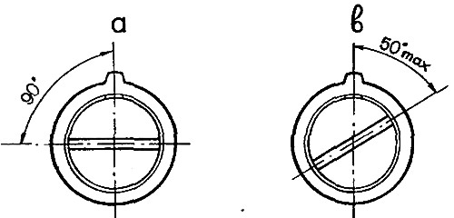
Pic. 2-89. Installation of restrictive sleeves on the screws for adjusting the idling system: a - on the screw of the amount of the mixture; c - on the mixture quality screw