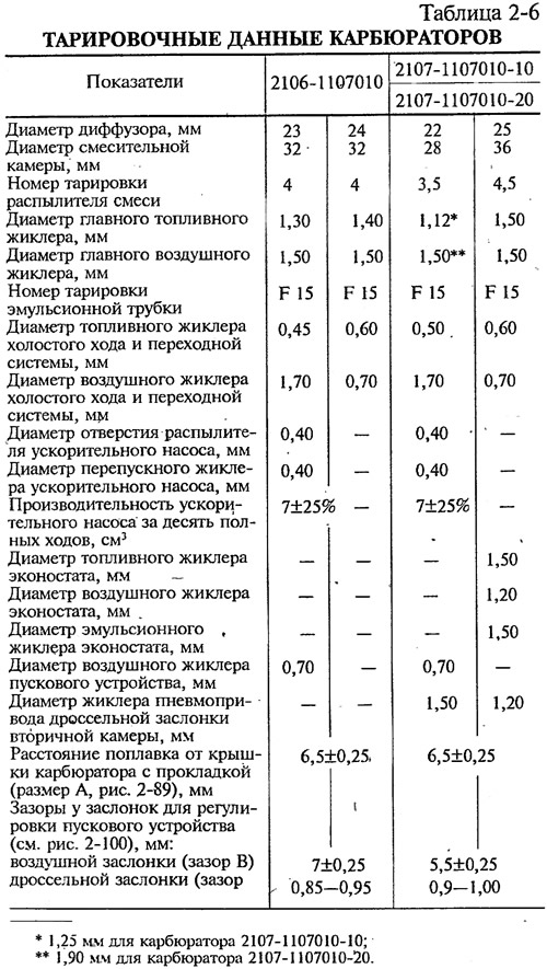
Carburetor 2106-1107010 emulsion type, two-chamber, with a falling stream. It has a balanced float chamber and a crankcase exhaust system for the throttle valve (see fig. 2-81). The idle system is equipped with heating of the throttle zone and an idle jet solenoid valve in the primary chamber (see fig. 2-82). Leverage provides consistent throttle opening and choke has a diaphragm starter for cold starting (pic. 2-83). accelerator pump (pic. 2-84) - diaphragm type, with a mechanical drive, supplies fuel to the primary chamber.
Pic. 2-81. Scheme of the main dosing system of the carburetor and econostat (the econostat atomizer is located in the secondary chamber of the carburetor. In the diagram, it is conditionally shown in the primary chamber): 1 - econostat emulsion jet *; 2 - emulsion channel of econostat*; 3 - econostat air jet *; 4 - econostat air jet *; 5 - econostat fuel jet *; 6 - needle valve; 7 - float axis; 8 - ball of the locking needle; 9 - float; 10 - float chamber; 11 - main fuel jet; 12 - emulsion well; 13 - emulsion tube; 14 - axis of the throttle valve of the primary chamber; 15 - spool groove; 16 - spool; 17 - large diffuser; 18 - small diffuser; 19 - atomizer
* Not available on carburetor 2106-11070i0
Pic. 2-82. Scheme of the idle system of the carburetor 2106-1107010: 1 - air jet; 2 - shut-off valve; 3 - fuel channel, 4 - emulsion well; 5 - throttle body; 6 - throttle valve of the primary chamber; 7 - screw-adjustable hole, 8 - transient openings, 9 - throttle body heating channel; 10 - adjusting screw; 11 - emulsion channel; 12 - adjusting screw for additional air; 13 - carburetor housing cover
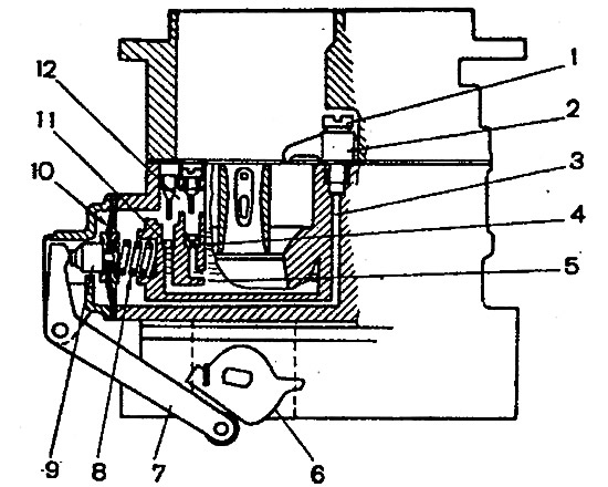
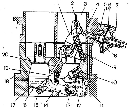
Pic. 2-83. Scheme of the starting device and the drive of the throttle valves of carburetors 2106-11070010: 1 - air damper control lever; 2 - air damper; 3 - air pipe of the primary chamber of the carburetor; 4 - thrust; 5 - rod of the starting device; 6 - diaphragm; 7 - adjusting screw; 8 - cavity communicating with the throttle space; 9 - telescopic rod; 10 - adjusting screw of the throttle valve of the primary chamber; 11 - throttle control lever; 12 - sector; 13 - axis of the throttle valve of the primary chamber; 14 - lever on the axis of the throttle valve of the primary chamber; 15 - axis of the throttle valve of the secondary chamber; 16 - throttle valve of the secondary chamber; 17 - lever; 18 - carburetor body; 19 - lever; 20 - thrust
Pic. 2-84. Accelerator pump diagram: 1 - ball supply valve; 2 - atomizer; 3 - fuel channel; 4 - bypass jet; 5 - float chamber; 6 - accelerator pump drive sector; 7 - drive lever; 8 - pump return spring; 9 - diaphragm cup, 10 - pump diaphragm; 11 - inlet ball valve; 12 - gasoline vapor chamber
Carburetor 2107-1107010-10 has other calibration data (see table 2-6), enrichment device (econostat), secondary chamber throttle actuator (pic. 2-85) and a modified idle system (pic. 2-86). There is no heated throttle body on these carburetors. Carburetor 2107-1107010-10 is fully interchangeable with carburetor 2106-1107010 and can be installed instead of it on cars manufactured before 1987.
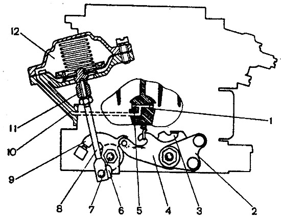
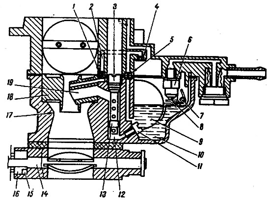
Pic. 2-85. Scheme of the throttle valve drive of the secondary chamber of carburetors 2107-1107010-10 and 2107-1107010-20: 1 - pneumatic drive jet located in the diffuser of the primary chamber; 2 - throttle actuator lever; 3 - lever rigidly connected to the axis of the throttle valve of the primary chamber; 4 - a lever that limits the opening of the throttle valve of the secondary chamber; 5 - pneumatic drive jet located in the diffuser of the secondary chamber; 6 - lever connected to lever 9 through a spring; 7 - axis of the throttle valve of the secondary chamber; 8 - shield of the pneumatic actuator; 9 - throttle control lever of the secondary chamber; 10 - channel for supplying vacuum to the pneumatic actuator; 11 - stem bushing; 12 - pneumatic actuator of the throttle valve of the secondary chamber
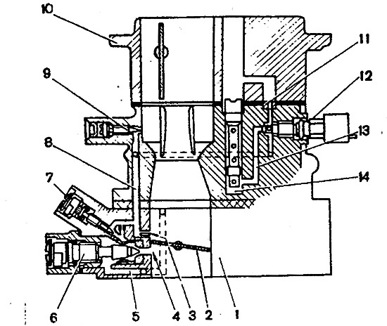
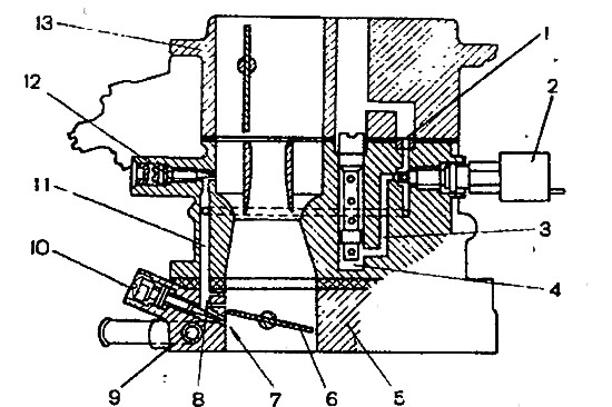
Pic. 2-86. Scheme of the idle system of carburetors 2107-1107010-10 and 2107-1107010-20: 1 - throttle body; 2 - throttle valve of the primary chamber; 3 - holes of transient modes, 4 - hole adjustable with a screw; 5 - air supply channel; 6 - adjusting screw for the amount of the mixture; 7 - composition adjusting screw (quality) mixtures; 8 - emulsion channel of the idle system; 9 - additional air adjusting screw *; 10 - cover of the carburetor body; 11 - air jet of the idle system; 12 - shut-off valve; 13 - fuel channel of the idle system; 14 - emulsion well.
* Installed on parts of carburetors
The carburetor 2107-1107010-20 differs from the carburetor 2107-1107010-10 in the changed diameters of some jets and the introduction of a pipe for supplying vacuum to the vacuum regulator of the ignition distributor. This carburetor can be installed instead of carburetor 2106-1107010 on cars manufactured before 1980. But instead of a conventional ignition distributor (without vacuum regulator) it is necessary to install the ignition distributor type 30.3706-02, which has a vacuum regulator.