
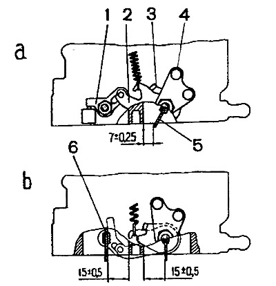
Pic. 2-99. Adjustment of the full and partial opening of the throttle valves of the carburetor 2106-1107010: a - adjustment of the partial opening of the damper of the primary chamber, c - adjustment of the position of the throttle damper of the secondary chamber; 1 - lever on the axis of the throttle valve of the secondary chamber, 2 - lever for driving the throttle valve of the secondary chamber; 3 - lever rigidly connected to the axis of the throttle valve of the primary chamber; 4 - damper drive lever; 5 - throttle valve of the primary chamber; 6 - throttle valve of the secondary chamber
Both throttle valves must be fully open when lever 4 is turned to the end position until the end of lever 3 rests against the special lug on the throttle body (pic. 2-99, in).
Adjust this position of the throttle valves by bending the lower antennae of the lever 3.
The position of the throttle valves of carburetors 2107-1107010-10 and 2107-1107010-20. Check the full opening of the throttle valves by turning the levers of their drive to the position against the stop. The value of the maximum opening of the throttle valve of the primary chamber (13±0.5mm) adjust by bending the lower end of the lever 3 (pic. 2-100). The value of the maximum opening of the throttle valve of the secondary chamber (17±0.5mm) adjust by screwing in or unscrewing the pneumatic drive rod.
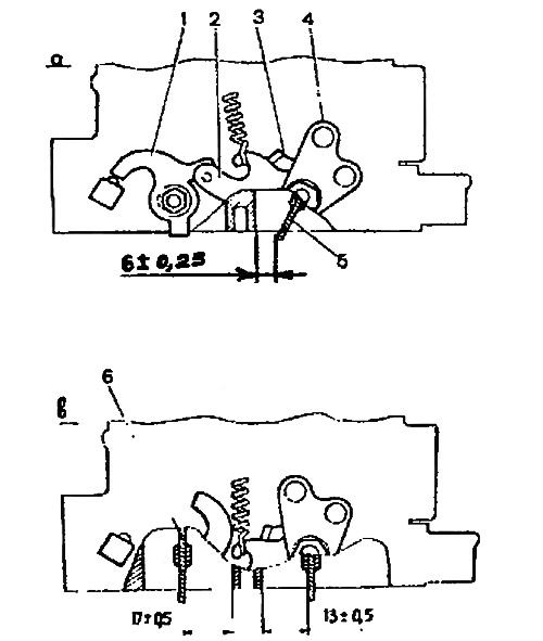
Pic. 2-100. Adjusting the position of the throttle valves of carburetors 2107-1107010-10 and 2107-1107010-20: a - partial opening of the throttle valve of the primary chamber; c - full opening of the throttle valves; 1 - lever on the axis of the throttle valve of the secondary chamber; 2 - throttle actuator lever of the secondary chamber; 3 - lever rigidly connected to the axis of the throttle valve of the primary chamber; 4 - damper drive lever; 5 - throttle valve of the primary chamber; 6 - throttle valve of the secondary chamber
Partial opening of the throttle valve of the primary chamber, in which the upper antennae of the lever 3 is in contact with the lever 2 (see fig. 2-101. A) should be 6±0.25 mm. This size is adjusted by bending the upper antennae of the lever 3.
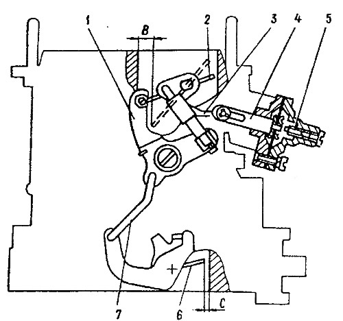
Pic. 2-101. Starter drive adjustment: 1 - air damper drive lever; 2 - air damper; 3 - thrust of the starting device, 4 - rod of the starting device; 5 - adjusting screw; 6 - throttle valve of the primary chamber; 7 - throttle actuator rod
Starting device. When turning lever 1 (pic. 2-101) counterclockwise until it stops, the air damper must be completely closed, and in this position of the lever, the end of the rod 3 must be at the end of the groove of the rod 4 of the starting device, but do not move the rod. This requirement is fulfilled by bending the rod 3.
With the air damper fully closed, the throttle damper of the primary chamber should be ajar by 0.85-0.95 mm (gap C - the distance between the damper and the chamber wall at the location of the vias of the idle system). This gap is adjusted by bending the rod 7.
A fully closed air damper should open 7±0.25 mm (clearance B) rod 4 of the starting device when moving it manually to the right until it stops. This value is adjusted by screw 5.
For carburetors 2107-1107010-10 and 2107-1107010-20, gap B should be 5.5±0.25 mm, and gap C should be 0.9-1.0 mm.
Accelerator pump performance tested in ten full turns (moves) lever 4 (pic 2-100) throttle control. fuel; what comes out of the pump sprayer during these ten strokes is collected in a beaker. Its volume should be 5.25-8.75 cm3. Before starting the test, make ten test moves with lever 4 to fill the channels of the accelerator pump.
Needle valve tightness tested on a stand that supplies fuel to the carburetor at a pressure of 30 kPa (3 m water column). After setting the level in the test tube of the stand, its fall is not allowed for 10-15 seconds. If the fuel level drops, this indicates a fuel leak through the needle valve.