
Disassembly
To disassemble the pump:
- detach body 5 (pic. 2-62) pump from cover 3;
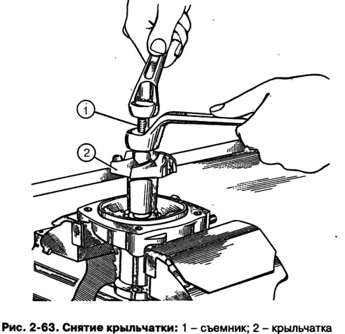
- secure the cover in a vise using spacers and remove the impeller 2 (pic. 2-63) from the roller with a puller A.40026;
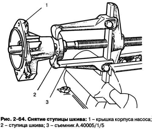
- remove hub 2 (pic. 2-64) fan pulley from the roller using a puller А.40005/1/5;
- unscrew the locking screw 8 (pic. 2-62) and remove the bearing with the pump shaft. The pressing force must be applied to the outer race of the bearing;
- remove gland 7 from housing cover 3.
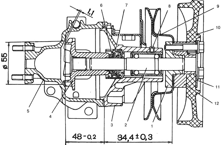
Pic. 2-62. Longitudinal section of the coolant pump:
1 - pulley hub; 2 - roller; 3 - cover; 4 - impeller; 5 - body; 6 - thrust ring; 7 - stuffing box; 8 - bearing lock screw; 9 - pulley; 10 - fan; 11 - overlay; 12 - fan hub.
Control
Check the axial clearance in the bearing. This operation must be done if significant pump noise is noted. The gap should not exceed 0.13 mm at a load of 49 N (5 kgf). With a larger clearance, replace the bearing assembly with the roller with new ones.
It is recommended to replace the pump seal and the gasket between the pump and the cylinder block with new ones during repairs.
Inspect the pump housing and cover for deformation or cracks.
Assembly
Assemble in the following order:
- install the stuffing box with a mandrel, avoiding distortion, into the housing cover;
- press the bearing with the shaft into the cover so that the seat of the locking screw coincides with the hole in the pump housing cover. The pressing force must act on the outer ring of the bearing;
- tighten the bearing lock screw and caulk the contours of the socket so that the screw does not loosen;
- press on with tool A.60430 (pic. 2-65) on the roller hub of the pulley, keeping the size (84,4±0,3) mm. If the hub is made of sintered metal, press only the new hub;
- press the impeller onto the roller using tool A.60430, ensuring the size (48-0,2) mm shown in Figure 2-62. In this case, the necessary clearance will be provided between the impeller blades and the pump housing;
- assemble the pump housing with the cover, placing a gasket between them.
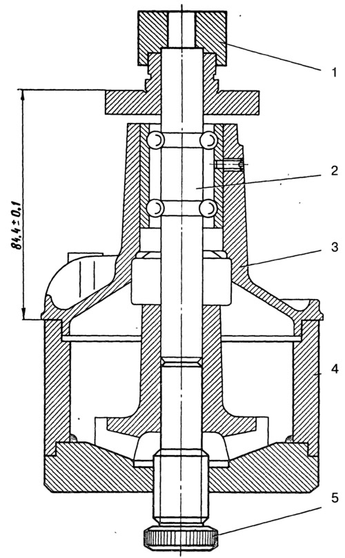
Pic. 2-65. Pressing the impeller onto the pump shaft with tool A.60430:
1 - support; 2 - pump roller; 3 - pump housing cover; 4 - glass; 5 - set screw.