




Secure the transfer case to a disassembly stand and loosen the flange mounting nuts on the drive shaft and on the front and rear axle drive shafts.
Loosen the fastening nuts and remove the housing 1 (Fig. 3-39) of the front axle drive complete with cover 2, lever, fork, differential lock clutch and the front axle drive shaft. Remove the housing 3 of the speedometer drive complete with the driven gear of the speedometer drive.
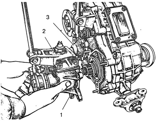
Fig. 3-39. Removing the front axle drive housing:
1 - front axle drive housing; 2 - crankcase cover; 3 - speedometer drive housing.
After removing the lock washer 8 (fig. 3-36), remove axle 10 and remove differential lock lever 11. Then remove cover 7 of the front axle drive housing and remove spring and ball of lock 19. Unscrew lock bolt 3 of the differential lock fork and remove rod 6, fork 1 and locking clutch 2.
Remove the back cover 31 (fig. 3-35) assembled with the rear axle drive shaft, making sure not to damage the sealing gasket. Then remove flanges 12 from the drive shaft and the front and rear axle drive shafts.
Remove the mounting rings of the bearings of the front and rear axle drive shafts. Remove shaft 11 (fig. 3-35) the front axle drive from the crankcase together with bearing 8, thrust ring and oil deflector 9. Remove the rear axle drive shaft from rear cover 31 together with bearing 36, thrust ring and oil deflector.
Remove cover 21 of the front bearing of the drive shaft and the inspection hatch cover.
Remove bracket 13 (fig. 3-36) of the gearshift lever assembly with the lever. Then, having removed the lock washer, take out the axle and remove the lever 14.
Loosen the locking bolt of the gear shift fork 17 and carefully, closing the retainer socket with your finger, remove the rod 12 and the retainer parts.
Remove the front cover 4 (Fig. 3-40) together with the differential, then install the differential bearing mounting ring and remove the bearing assembly with the differential from the front cover.
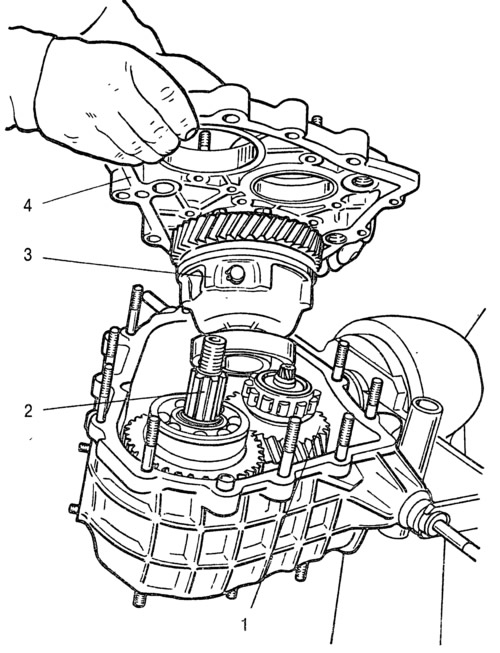
Fig. 3-40. Removing the front cover of the transfer case:
1 - intermediate shaft; 2 - drive shaft; 3 - differential; 4 - front cover.
The original is available on the online resource vazbook.ru
Remove the mounting rings from the rear bearings of the drive and intermediate shafts and remove both shafts from the transfer case housing: the drive and intermediate shafts.
Clamp the drive shaft in a vice and remove the thrust ring and rear bearing 11 (Fig. 3-41) using a universal puller. Remove the low gear pinion 9 together with the bushing 10, the gear shift clutch 8, the clutch hub 7, and the high gear pinion 6 from the drive shaft.
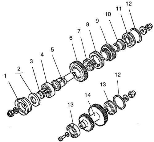
Fig. 3-41. Details of the drive and intermediate shafts:
1 - flange; 2 - oil seal; 3 - thrust bearing ring; 4 - front bearing; 5 - drive shaft; 6 - top gear; 7 - hub; 8 - coupling; 9 - low gear; 10 - bushing; 11 - rear bearing; 12 - bearing mounting ring; 13 - intermediate shaft bearings; 14 - intermediate shaft.
Disassemble the differential, for which:
- remove the retaining ring 1 (Fig. 3-42) and the spring washer 2 of the front bearing;
- remove the rear and front bearings from the differential housing (Fig. 3-43) using the universal puller and stop 67.7853.9559;
- unscrew the bolts securing the differential driven gear, mark their relative positions with marks on the differential housings and separate the housings;
- remove the differential driven gear;
- remove the retaining rings 8 (Fig. 3-42) and spring washer 14, then press out the satellite axle and remove the satellites and drive gears of the drive axles with support washers.
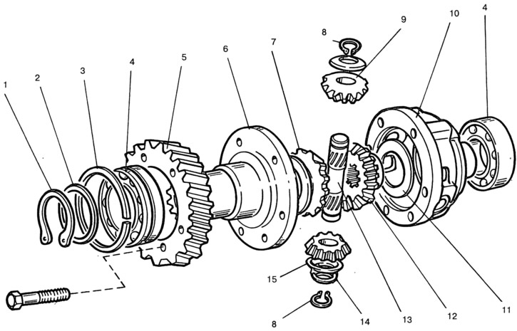
Fig. 3-42. Transfer case differential parts:
1 - retaining ring; 2 - spring washer; 3 - bearing mounting ring; 4 - differential housing bearings; 5 - driven gear; 6 - front differential housing; 7 - front axle drive gear; 8 - satellite axle retaining ring; 9 - satellite; 10 - rear differential housing; 11 - support washer; 12 - rear axle drive gear; 13 - satellite axis; 14 - spring washer of the satellite axle; 15 - support washer.
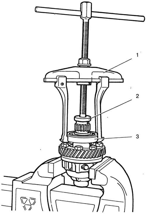
Fig. 3-43. Pressing the bearing from the differential housing:
1 - puller A.40005/1/6; 2 - stop 67.7853.9559; 3 - bearing.
Press out worn or damaged seals from the front axle housing, from the front bearing cap and from the rear cover. Unscrew the nuts from the suspension cushion axles and remove the brackets as a whole.