
Removing
Place the vehicle over a pit or on a lift. Release the parking brake lever and place the transfer case and transmission shift levers in the neutral position. Turn away screws of fastening of facing of an upholstery of a casing of a floor and remove facing. Remove the handles from the levers and the outer covers. Loosen the mounting screws and remove the lever hatch cover and the inner cover of the lever seal.
Disconnect the speedometer drive flexible shaft from the transfer case and the wires from the differential lock warning light sensor. Turning the cardan shafts, disconnect the flanges of the cardan shafts from the shafts of the transfer case, and the flange of the intermediate cardan shaft from the flange of the output shaft of the gearbox.
Loosen nuts 3 (pic. 3-37) bolts of fastening of brackets 1 suspension (supports) transfer box and remove it together with the brackets and gaskets 5, which are installed under the brackets, and assembled with the intermediate shaft. Mark each gasket so that you can put them in place in the same number.
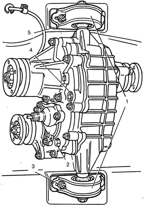
Pic. 3-37. Mounting the transfer case on the car:
1 - transfer box suspension brackets; 2 - filler plug; 3 - nut for fastening the suspension bracket; 4 - drain plug; 5 - shims.
Installation and centering
Install and center the transfer case in the following order:
- make sure the engine mounts are properly installed in the brackets (the centering washers of the front engine mounts must fit into the corresponding holes in the side brackets) and a snug fit of the transfer case supports to the bottom of the body. If necessary, straighten the surface of the body under the supports;
- install the transfer box on the car without fully tightening the bolts 4 and 5 (pic. 3-38) mounting brackets for the transfer box suspension;
- moving the transfer case up and down, as well as in the vertical direction, find a position in which the flanges of the drive shaft of the transfer case and the intermediate shaft of the driveline will be at the same level, parallel and the gap between them is minimal; in this case, the shafts of the transfer case must be parallel to the bottom of the body;
- by installing previously removed shims under the suspension brackets (supports), fully tighten the nuts securing the transfer box suspension brackets;
- attach the front and rear cardan shafts to the transfer case shafts; connect the flexible shaft to the speedometer drive, and the wires to the differential lock warning light sensor.
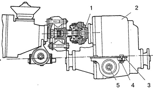
Pic. 3-38. Transfer box installation diagram:
1 - stud for fastening the flanges of the intermediate cardan shaft and the drive shaft of the transfer case; 3 - shims; 4 - nuts for fastening the transfer case to the body; 5 - nuts for attaching the transfer box suspension brackets to the axles.
When replacing the transfer case, as well as when «draft» the rear engine mount, which caused the transfer case to vibrate, it is necessary to select and install a new thickness of the gaskets 5 (pic. 3-37).
The procedure for selecting shims is as follows:
- make sure the engine mounts are properly installed in the brackets (see subsection. «Removal and installation of the engine»);
- disconnect the flanges of the transfer case input shaft and the intermediate shaft of the driveline;
- loosen the nuts securing the transfer case supports to the body, remove the shims and, moving the transfer case along and across the body, as well as in the vertical direction, find such a position in which the disconnected flanges will be at the same level, parallel and the gap between them is minimal, and transfer box shafts are parallel to the bottom of the body;
- the resulting gap between the floor of the body and the supports fill with the required number of gaskets;
- align the centering flanges of the flanges without creating an interference in the transfer case and engine supports, and, holding the transfer case in this position, tighten the previously loosened nuts of the transfer case supports;
- insert and fasten the bolts for fastening the flanges of the transfer case and the intermediate shaft; if the bolts pass freely into the holes of the flanges, then the alignment is carried out correctly, otherwise repeat the operations to align the flanges.