
Disassemble the carburetor cover, for which the following operations are performed. Unscrew the needle valve seat 15 (pic. 53) and branch pipe 1 of the fuel supply, take out the fuel filter 2. Having unscrewed the axis 11, take out the ball 13 with the spring, remove the lever 10 of the air damper control. Disconnect the spring 12 of the air damper lever.
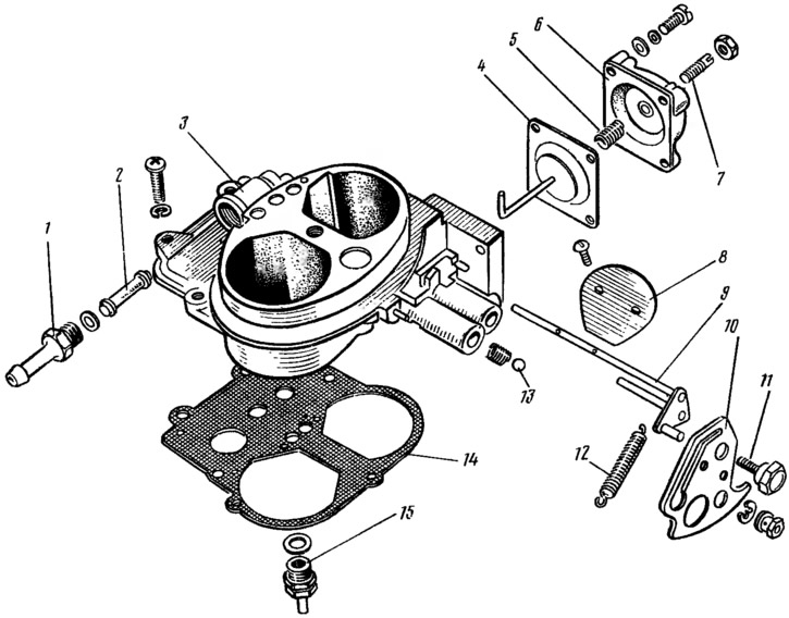
Pic. 53. Carburetor cap details: 1 - fuel supply pipe; 2 - fuel filter; 3 - carburetor cover; 4 - diaphragm of the starting device with a rod; 5 - spring; 6 - starter cover; 7 - adjusting screw; 8 - air damper; 9 - axis of the air damper with a lever; 10 - air damper control lever; 11 - axis of the lever; 12 - air damper lever spring; 13 — a ball of fixing of the lever of management of an air damper; 14 - gasket; 15 - needle valve.
If necessary, unscrew the screws securing the air damper 8, remove the damper and axle 9. Disassemble the diaphragm trigger by removing the cover 6 assembly with the adjusting screw 7. Remove the spring 5 and diaphragm 4 with the stem.
Disassemble the carburetor body. Carefully remove the float 19 from the body (pic. 54). The housings of the fuel jet 17 of the transition system of the second chamber and the idle fuel jet with an electromagnetic shut-off valve 11 are unscrewed, the jets are removed. Remove the cover 10 of the accelerator pump with the drive lever, the diaphragm 9 and the spring. The accelerator pump atomizers are taken out by the body 5, the main air jets 7 with emulsion tubes 6 are unscrewed. Having unscrewed the plugs 4 of the float chamber, the main fuel jets 3 of the main metering systems are unscrewed through the holes.
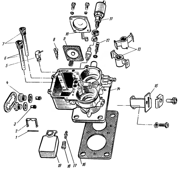
Pic. 54. Details of the carburetor body: 1 - axis of the float; 2 - stop axis of the float; 3 - main fuel jets of the first and second chambers; 4 - cork; 5 - body of sprayers of the accelerating pump; 6 - emulsion tubes; 7 - main air jets of the first and second chambers; 8 — adjusting screw of the accelerator pump; 9 - accelerator pump diaphragm; 10 - accelerator pump cover with drive lever; 11 - shut-off solenoid valve with idle fuel jet; 12 - adjusting screw for additional idle air of factory adjustment; 13 - sprayers of the first and second chambers; 14 - carburetor body; 15 - bracket for fastening the shell of the air damper drive rods; 16 - heat-insulating gasket; 17 - fuel jet of the transition system of the second chamber; 18 - housing of the fuel jet of the transition system of the second chamber; 19 - float.
The throttle body is disassembled, for which the following operations are performed. Take out the plastic cap with a corkscrew 7 (pic. 55) and unscrew the adjusting screw 8 quality (composition) idle mixture. Having unscrewed the fastening screws, remove the housing 10 of the adjusting screw and the sealing gasket 11. The adjusting screw 29 of the amount of the mixture is unscrewed. Unscrew nuts 18 and 22 from axes 1 to 4 throttle valves; bending the tab of the lock washer 19, remove the levers 20, 15, 12 and 24 from the axles.
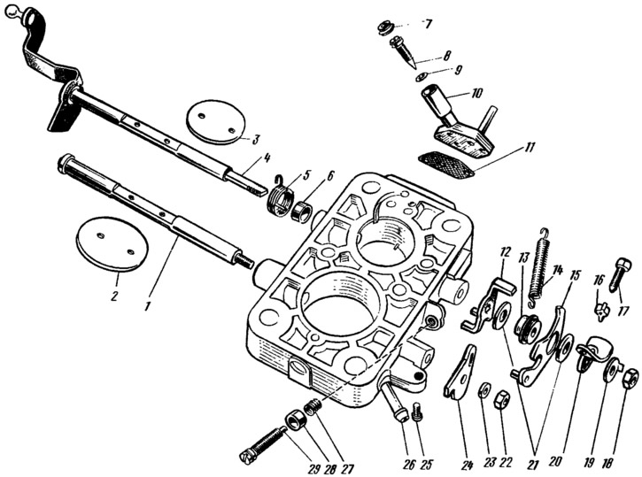
Pic. 55. Throttle body parts: 1 - axis of the throttle valve of the second chamber; 2 - throttle valve of the second chamber; 3 - throttle valve of the first chamber; 4 - axis of the throttle valve of the first chamber with a drive lever; 5 - throttle return spring of the first chamber; 6 - sleeve; 7 - plastic plug; 8 - quality adjusting screw (composition) idle mixtures; 9 — a sealing ring of the adjusting screw; 10 - body of the adjusting screw; 11 - sealing gasket; 12 - throttle axis lever of the first chamber; 13 - sleeve; 14 - throttle return spring of the second chamber; 15 - throttle actuator lever of the second chamber; 16 - stopper; 17 - adjusting screw for slightly opening the throttle valve of the first chamber; 18, 22 - nuts; 19 - lock washer; 20 - lever; 21, 23 - washers; 24 - throttle lever of the second chamber; 25 - adjusting screw for the completeness of closing the throttle valve of the second chamber; 26 - branch pipe for suction of crankcase gases into the throttle space of the carburetor; 27 - spring; 28 - cap (screwdriver catcher); 29 - adjusting screw for the amount of idle mixture.
The carburetor is assembled in the reverse order of disassembly. At the same time, attention is paid to the float, which must rotate freely on its axis without touching the walls of the float chamber, as well as to the needle valve, which must slide freely in its seat, without distortions and jamming.
In order not to confuse the jets during assembly, it is necessary to pay attention to the marking of the jets and, when installing them, be guided tab. 3.
Emphasis 2 (see fig. 54) put a notch on a horizontal shelf towards the float 19. When assembling the accelerator pump, bait the cover fastening screws, press the drive lever all the way, tighten the screws and release the lever.