
Disassembly
Unscrew the screws securing the carburetor cover and carefully disconnect it from the body so as not to damage the gasket, float, econostat tubes and the transition system of the second chamber.
Disassemble the lid (pic. 41) carburetor in the following order. With a mandrel 03X24.5 mm, carefully push the axis 1 of the float 3 out of the racks and, without damaging the tongues of the float, disconnect it from the cover. Remove the gasket 4, unscrew the needle valve seat 2. Unscrew the fuel supply pipe 11 and remove the fuel filter 12.
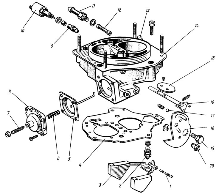
Pic. 41. Carburetor cap details: 1 - float axis; 2 - needle valve; 3 - float; 4 - gasket; 5 - diaphragm of the starting device with a rod; 6 - spring; 7 - adjusting screw; 8 - starter cover; 9 - idle fuel jet; 10 - electromagnetic shut-off valve; 11 - fuel supply pipe; 12 - fuel filter; 13 - fuel drain pipe; 14 - carburetor cover; 15 - air damper; 16 axis air damper with lever; 17 - ball for fixing the air damper control lever; 18 air damper control lever; 19 - lever axis; 20 - bushing for fastening the air damper drive rod
The housing of the idle fuel jet 9 with the electromagnetic shut-off valve 10 is unscrewed and the jet is removed. The axle 19 is unscrewed, the ball 17 with the spring is removed, the air damper control lever 18 is removed, the air damper lever spring is disconnected. If necessary, unscrew the screws securing the air damper, remove the damper 15 and axle 16.
The diaphragm trigger is disassembled by removing the cover 8 assembly with the adjusting screw 7. The spring 6 and the diaphragm 5 with the stem are removed. Disassemble the carburetor body (pic. 42). To do this, remove the cover 3 of the accelerator pump with the lever 2 and the diaphragm 1 with the spring. Take out the nozzles 10 and 11 of the accelerating pump and the nozzles of the first and second chambers. Atomizers 10 of the accelerating pump are removed only by the body of the atomizers.
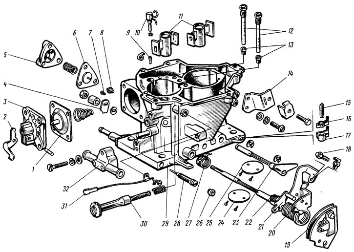
Pic. 42. Details of the carburetor body: 1 - accelerator pump diaphragm; 2 - accelerator pump drive lever; 3 - cover; 4 - accelerator pump drive cam; 5 - power modes economizer cover; 6 - economizer diaphragm; 7 - economizer fuel jet; 8 - economizer valve; 9 - check valve of the accelerator pump; 10 - sprayed and accelerator pump with fuel supply valve; 11 - sprayers; 12 - main air jets with emulsion tubes; 13 - main fuel jets; 14 - bracket for fastening the shell of the draft of the air damper drive; 15 - adjusting screw of the second chamber; 16 - adjusting screw stopper; 17 - stopper cap; 18 - adjusting screw for slightly opening the throttle valve of the first chamber; 19 - throttle control sector; 20 - axis of the throttle valve of the first chamber with drive levers; 21 - lock lever of the second chamber; 22 - lock lever spring; 23 - axis of the throttle valve of the second chamber with a lever; 24 - throttle valve of the first chamber; 25 throttle valve of the second chamber; 26 plug; 27 - return spring of the throttle actuator lever of the second chamber; 28 - quality adjustment screw (composition) idle mixtures; 29 - carburetor body; 30 - adjusting screw for the amount of idle mixture; 31 - electrical wire of the forced idle economizer limit switch; 32 - carburetor heating block
Unscrew the nut of the throttle valve axis of the first chamber, remove the cam 4 of the accelerator pump drive and the washer. The fastening screw is unscrewed and the electrical wire 31 with the forced idle economizer limit switch is removed from the adjusting screw 30 of the idle mixture amount. If necessary, unscrew the screw 30. Remove the plastic plug 26 with a corkscrew and unscrew the quality adjusting screw 28 (composition) idle mixture.
Remove the cover 5 of the power mode economizer, diaphragm 6 and spring. The fuel jet 7 of the economizer is turned out. The main air jets 12 with emulsion tubes and the main fuel jets 13 of the main metering systems are unscrewed.
If necessary, the screws for fastening the throttle valve 24 of the first chamber are unscrewed, the valve is removed and the axle 20 is assembled with the drive levers. After removing the lock washer and unscrewing the screws securing the throttle valve 25 of the second chamber, remove the damper and take out the damper axis. Take out the bearings of the axes of the throttle valves of the first and second chambers.
Assembly
The carburetor is assembled in the reverse order. In doing so, pay attention to the following:
- the float must rotate freely on its axis without touching the walls of the chamber;
- the needle valve should slide freely in its seat, without distortions and jamming;
- in order not to confuse the jets during assembly, you need to pay attention to the marking of the jets and be guided when installing them tab. 2;
- after tightening the screws for fastening the throttle valves, they caulk the screws on a special device that does not allow deformation of the axes of the dampers;
- when assembling the accelerator pump, the screws for fastening the cover 3 are baited, the lever 2 of the pump drive is pressed all the way, the screws of the cover are finally screwed in and the lever 2 is released.