
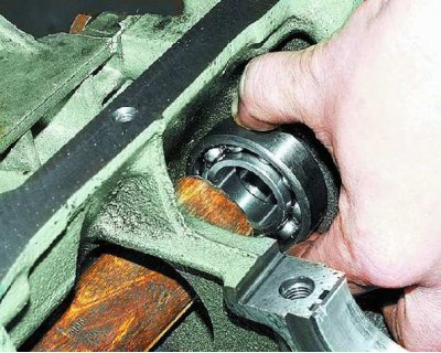
138. Install the bearing circlips, press the plugs with a thin layer of sealant, and the front bearings of the balance shafts into the cylinder block seats. Press in the bearings with a mandrel (Dnar.=50 mm, dext.=30mm, L=100mm), applying force to the outer rings. Press bearings from the inside of the block of cylinders.
139. Install balance shafts.
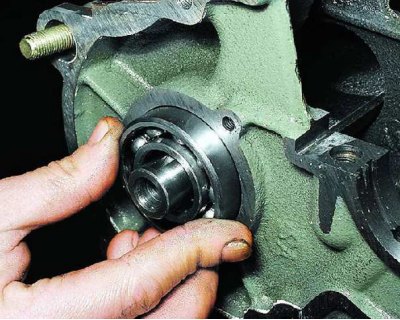
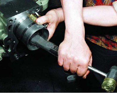
140. Install the rear balance shaft bearings and press them in with a suitable drift, applying pressure to the outer race of the bearing.
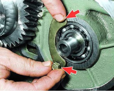
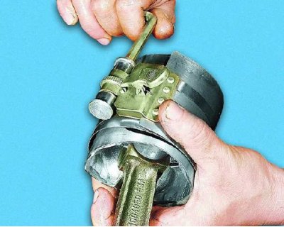
141. Install the balance shaft rear bearing circlips using special pliers.
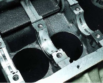
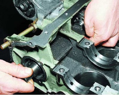
142. Lubricate the crankshaft main bearing shells with a thin layer of engine oil and install them in the bed of the cylinder block (install the fixing mustaches of the liners in the grooves of the beds). The middle neck liner does not have a longitudinal groove.
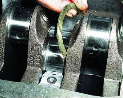
143. Install the engine crankshaft in the bed of the cylinder block, after lubricating the shaft journals (main and connecting rod) thin layer of engine oil. Install the thrust half rings on the middle neck of the crankshaft, having previously lubricated them with a thin layer of engine oil (grooves towards the necks of the shaft, install the ring with a white aluminum coating on the front side of the crankshaft bed, and the cermet ring on the other side of the bed). Rotate the half rings so that their ends are flush with the end of the bed.
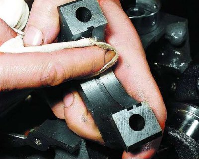
144. Wipe the main bearing caps with a clean cloth.
145. Lubricate the liners with a thin layer of engine oil and install them in the main bearing caps (install the fixing mustaches of the liners in the grooves of the covers).
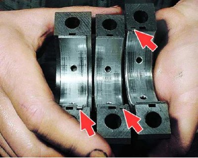
146. Install the main bearing caps according to the marks on them (one mark - the first cover from the side of the front end of the crankshaft, two marks - the second, three - the third). The labels on the covers must be located on the side of the generator.
147. Tighten bolts of fastening of covers of radical bearings the moment 68,31–84,38 N/m (6.97–8.61 kgf/m). First of all, you need to tighten the bolts of the middle cover.
148. Check if the crankshaft turns. It should rotate easily, without jamming.
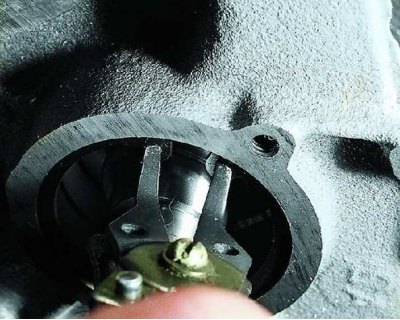
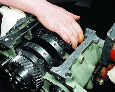
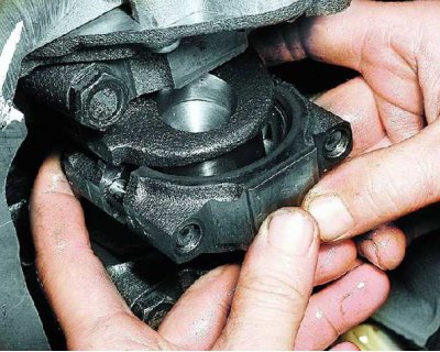
149. Install the thrust plates of the rear bearings of the balancing shafts and tighten the bolts of their fastening (two bolts on each plate).
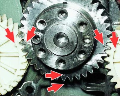
150. Turn the crankshaft so that the mark on the balance shaft drive gear matches the lug on the cylinder block. Install the keys in the grooves of the rear ends of the balance shafts and the balance shaft gears. The wide mark on the balance shaft gear should align with the double mark on the crankshaft gear, and the narrow mark on the other balance shaft gear with the single mark on the crankshaft gear.
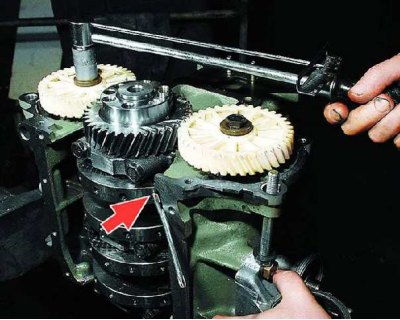
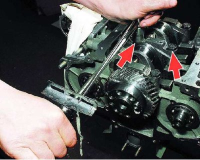
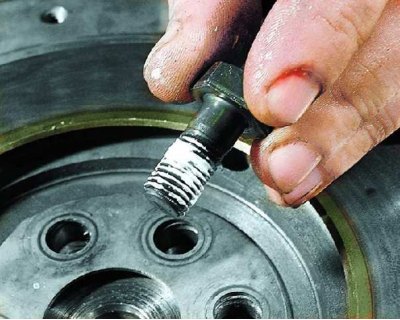
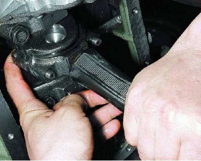
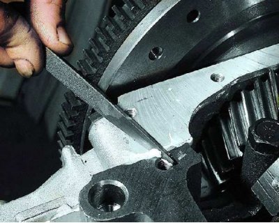
151. Tighten the gear mounting bolts to a torque of 45.82–56.60 N/m (4.68–5.78 kgf/m). To do this, fix the crankshaft from turning by inserting a metal rod into the balancing hole.
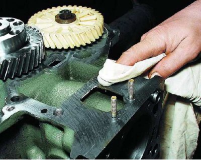
152. Degrease the mating surface of the crankshaft rear oil seal holder and...
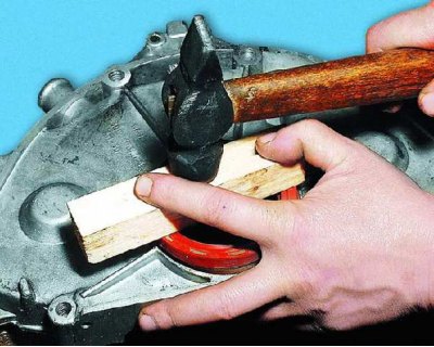
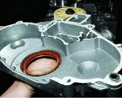
153. Press the gland into the holder (using a wooden block).
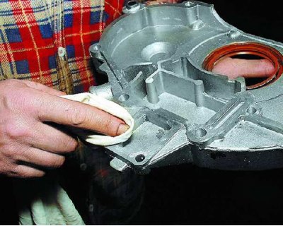
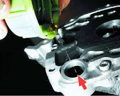
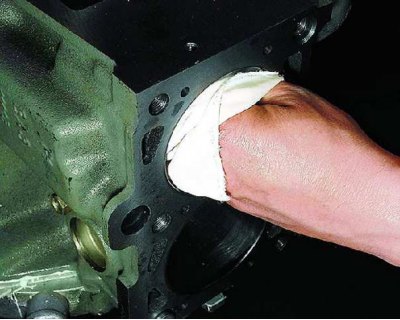
154. Degrease the surface of the cylinder block with gasoline, observing fire safety measures.
155....apply a thin layer of sealant to this surface.
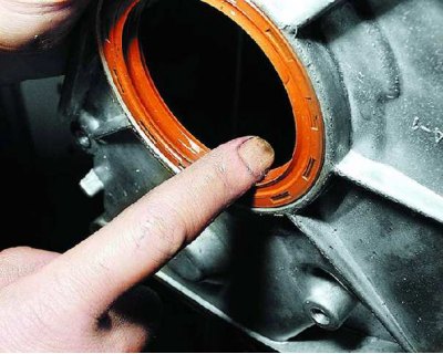
156. Lubricate the working lip of the crankshaft rear oil seal with a thin layer of engine oil.
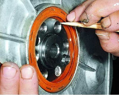
157. Install the crankshaft rear oil seal holder to the engine. Fill the working edge of the stuffing box with a wooden stick.
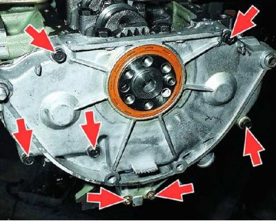
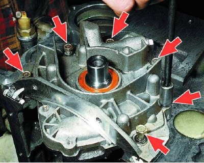
158. Tighten the five bolts and two nuts of the crankshaft rear oil seal holder.
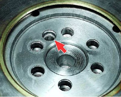
159. Install the flywheel on the crankshaft with the clutch pins facing out, aligning the marked hole with the bushing on the crankshaft flange.
160. Install the flywheel bolt plate, apply a thin coat of sealant to the flywheel bolts and...
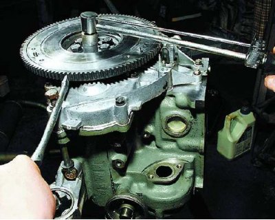
161.... while holding the flywheel from turning, tighten the bolts of its fastening to a torque of 70.81–87.47 N / m (7.22–8.92 kgf/m). Tighten the bolts crosswise.
162. For ease of installation of the oil pump, lubricate the pump gasket with a thin layer of grease (Litol-24) and install it on the surface of the cylinder block.
163. Pour 10–20 g of engine oil into the oil pump housing and...
164.... turn the oil pump gears a few turns to lubricate them. Gears should rotate easily, without jamming.
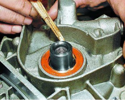
165. Install the oil pump assembly on the mating surface of the cylinder block (see subsection 10.8.2.), fill the working edge of the front oil seal with a wooden stick and...
166. Wrap six bolts of fastening of the oil pump to the block of cylinders.
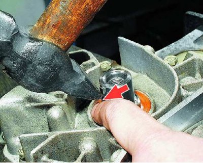
167. Install the key into the groove in the front end of the crankshaft.
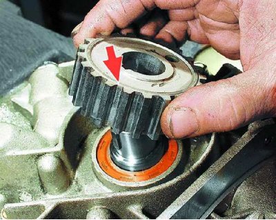
168. Install the crankshaft pulley and...
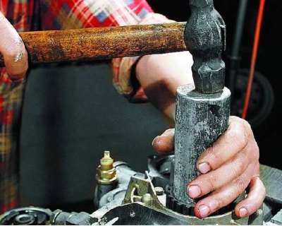
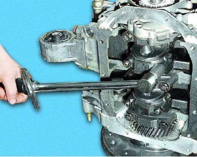
169....press it onto the shaft using a soft metal mandrel.
170. Wipe the cylinder mirrors with a clean cloth. Match pistons to cylinders by diameter (group marking is applied on the flange of the oil sump mounting of the cylinder block on the piston crown) and mass.
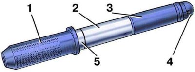
171. Slide the piston pin 2 onto the shaft 1 of the piston pin installer with spacer ring 5. Then put on the guide sleeve 3 and secure it with the screw 4 without tightening the screw. Distance ring dimensions: outer diameter 22 mm, inner diameter 15 mm, thickness 4 mm.
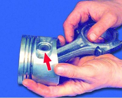
172. Heat the connecting rod head to 240°C in an oven for 15 minutes. Clamp the connecting rod in a vise, install the piston on it so that the holes for the pin coincide, and insert the fixture with the pin into the holes of the piston and connecting rod until it stops. To properly install the pin, the piston must be pressed with the boss against the upper head of the connecting rod in the direction of pressing. Note that...
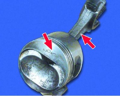
173.... the piston is mounted on the connecting rod so that the arrow on the piston head is directed in the opposite direction from the part number cast on the connecting rod. If there is an oil outlet hole on the bottom end of the connecting rod, the arrow on the piston must point towards that hole.
174. After the connecting rod has cooled, lubricate the piston pin through the hole in the piston bosses.
175. Wipe the pistons and connecting rods with a clean rag. Install piston rings (see operations 100–103).
176. Install the connecting rod bearing shells into the connecting rod and lubricate them with engine oil.
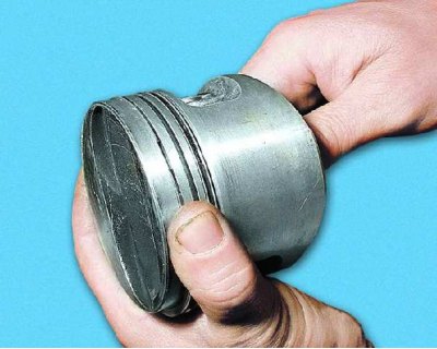
177. Check the ease of movement of the rings in the piston grooves by rotating the rings. Place the locks of the rings at an angle of 120°.
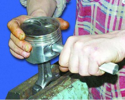
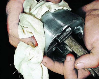
178. Using a special mandrel, compress the piston rings and...
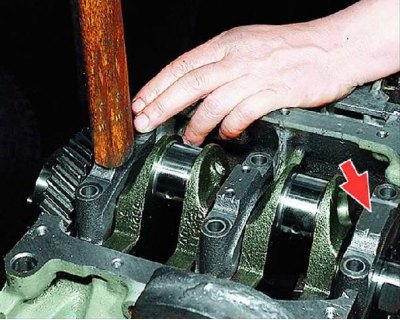
179.... Gently hitting the piston bottom with a hammer handle, install the piston assembly with connecting rods into the cylinder so that the arrow on the piston bottom is directed towards the camshaft drive. In this case, the mandrel must be firmly pressed against the cylinder block, otherwise the piston rings can be broken.
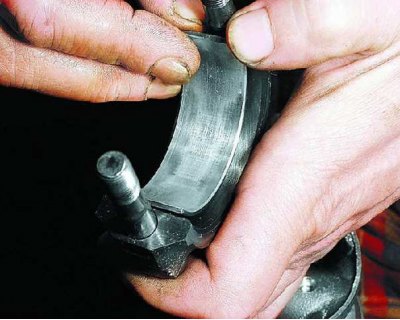
180. Install the connecting rod caps with liners on the connecting rod bolts (in this case, the number of the cylinder on the connecting rod and its cover must be located on one side) And...
181....siege them with the hammer handle.
182. Tighten the connecting rod bearing cap nuts to 43.32–53.51 N/m (4.42– 5.46 kgf/m).
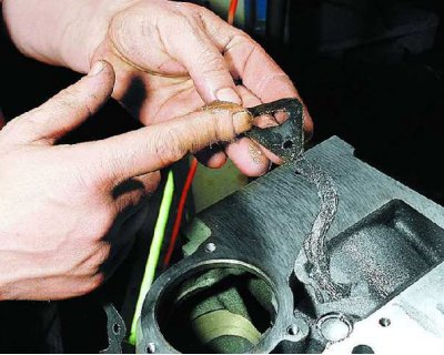
183. Remove the protruding parts of the oil pump gasket and excess sealant from the mating surface of the cylinder block under the oil sump.
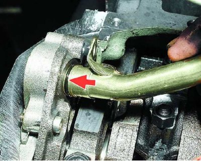
184. Install oil receiver with sealing ring (shown by arrow) and tighten the three mounting bolts.
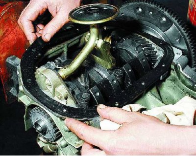
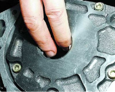
185. For ease of installation of the crankcase, lubricate the oil sump gasket with a thin layer of grease and install it on the surface of the cylinder block.
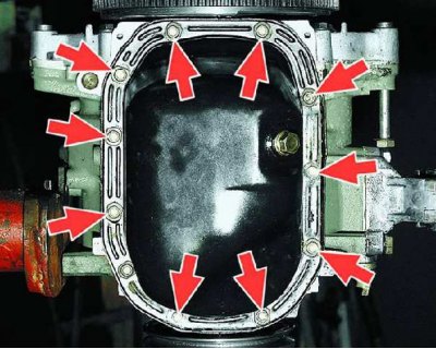
186. Install the oil sump and tighten the eleven bolts of its fastening.
187. Install the cylinder head (see subsection 10.4.1.). Next, assemble the engine in the reverse order of disassembly. Install the engine on the subframe (see steps 1-40). Adjust the tension of the camshaft and alternator drive belts.