
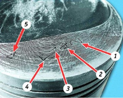
The following data is stamped on the bottom of the piston:
1 - piston class according to the hole for the finger (1, 2, 3)
2 - piston class by diameter (A, B, C, D, E)
3 - arrow showing the direction of installation of the piston
4 - group by weight (normal - "G", increased by 5 g - " ", reduced by 5 g - "-")
5 - repair size (diameter increased by 0.4 mm - D, by 0.8 - E)
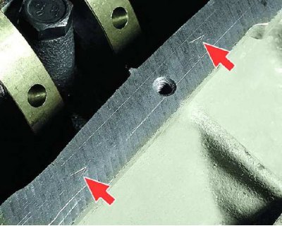
Cylinder class (A, B, C, D, E) embossed on the bottom plane of the block (mating plane under the oil sump).
Pistons selection
For the convenience of selecting pistons for cylinders by diameter, they are divided into five classes: A, B, C, D, E (through 0.1 mm). Spare parts are supplied with nominal size pistons in three classes A, C, E and two oversizes. The first repair size is increased by 0.4 mm, the second - by 0.8 mm.
By weight, the pistons are divided into three groups: normal, increased by 5 g and reduced by 5 g. Pistons of the same group must be installed on the engine.
For pistons of repair dimensions, rings of repair dimensions increased by 0.4 and 0.8 mm are supplied as spare parts. On the rings of the first repair size, a number is engraved "40", and the second "80".
Nominal dimensions of cylinder and piston diameters, mm
Size group | VAZ-1111 engine | Engine VAZ-11113 | ||
Cylinder | Piston | Cylinder | Piston | |
A B C D E | 76,00-76,01 76,01-76,02 76,02-76,03 76,03-76,04 76,04-76,05 | 75,965–75,975 75,975–75,985 75,985–75,995 75,995–76,005 76,005–76,015 | 82,00–82,01 82,01–82,02 82,02–82,03 82,03–82,04 82,04–82,05 | 81,965–81,975 81,975–81,985 81,985–81,995 81,995–82,005 82,005–82,015 |
When selecting pistons for cylinders, determine the gap between them as the difference between the measured diameters of the piston and cylinder.
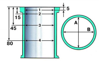
Cylinder measurement scheme:
A and B - measurement directions
1, 2, 3 and 4 - belt numbers
The nominal gap is set to 0.025-0.045 mm, the maximum allowable gap is 0.15 mm. If the gap does not exceed 0.15 mm, pistons from subsequent classes can be selected so that the gap is as close to the nominal as possible. If the clearance exceeds 0.15 mm, bore the cylinders to the next oversize and install pistons of the correct oversize. Under the repair size, both cylinders are bored, even if the gap between the piston and the cylinder exceeds the maximum allowable in only one cylinder.
Piston pins are divided by diameter into three classes (1, 2, 3) through 0.004 mm. The class of the finger is marked on its end face with paint. The piston pin class is stamped on the piston crown, and the connecting rod pin class is stamped on the connecting rod cap.
Size classes of piston pins and pistons
Class | Diameter, mm | Marking | ||
finger | holes in the piston | finger | piston | |
1 2 3 | 21,970–21,974 21,974–21,978 21,978–21,982 | 21,982–21,986 21,986–21,990 21,990–21,994 | Blue Green Red | 1 2 3 |
106. Clean the piston head from carbon deposits.
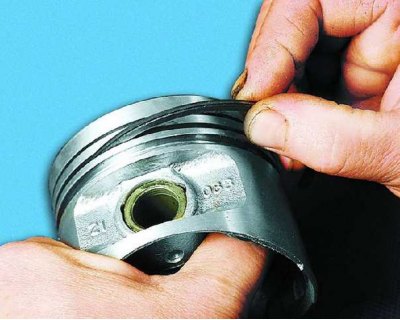
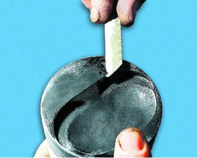
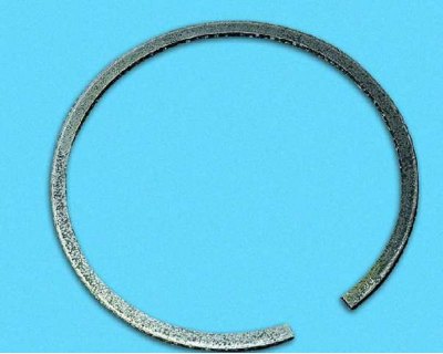
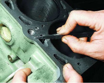
107. Clean the grooves for the piston rings. It is convenient to do this with a piece of the old ring.
108. Clean the oil drain holes with a suitable wire thickness.
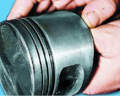
109. If the piston has scuff marks, traces of burnout, deep scratches, cracks, replace the piston.
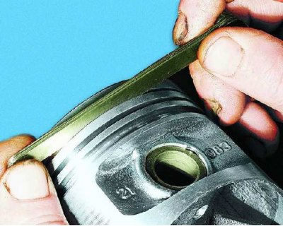
110. Check the clearance between the rings and grooves on the piston. To do this, using a set of feelers, measure the width of the grooves in several places along the circumference, and then...
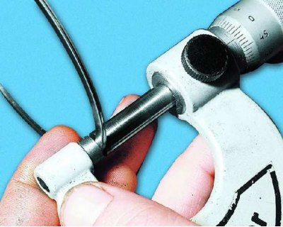
111.... measure the thickness of the rings with a micrometer in several places around the circumference. Calculate Average Clearances (difference between ring thickness and groove width). If at least one of the gaps exceeds the maximum allowable, replace the piston with rings.
Explanation of operations 110 and 111
Nominal clearance, mm:
- for the upper compression ring 0.04-0.075;
- lower compression ring 0.03-0.065;
- oil scraper ring 0.02-0.055.
The maximum allowable clearance for all rings is 0.15 mm.
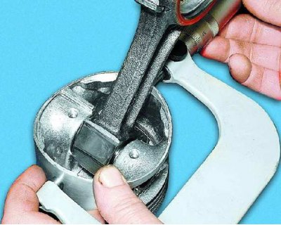
112. Measure the gaps in the locks of the rings. This can be done by inserting the ring into a special mandrel. If there is no mandrel, insert the ring into the cylinder (in which it worked), move the piston, like a mandrel, the ring into the cylinder so that it is installed in it without distortions, remove the piston from the cylinder and...
113.... with a feeler gauge, measure the gap in the lock of the ring. The nominal clearance should be 0.25-0.45 mm, the maximum allowable (due to wear) - 1.0 mm. If the gap exceeds the limit, replace the ring.
114. If the gap is less than 0.25 mm, carefully grind off the ends of the ring with a needle file.
115. Examine the cylinders. If there are scratches, scuffs, shells, etc. on the cylinder mirror, bore the cylinders to the repair size or replace the cylinder block. With such defects with a depth of more than 0.8 mm, the unit cannot be repaired and must be replaced.
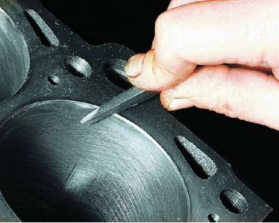
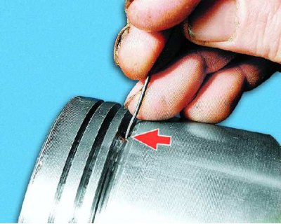
116. Clear a deposit in the top part of cylinders. If a belt has formed there due to cylinder wear, remove it with a scraper. Blunt the sharp edges on the plane of the cylinder block with a scraper...
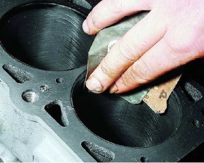
117....and then fine sandpaper. Measure the bore diameter of the cylinder in two perpendicular planes (along and across the axis of the cylinder block) and four belts.
118. Measure the piston diameter at a distance of 51.5 mm from its bottom in a plane perpendicular to the piston pin. Calculate clearances between pistons and cylinders.
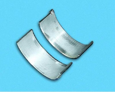
119. Inspect the connecting rod bearings. If they have cracks, scuffs, chipping, replace the liners. It is forbidden to carry out any adjustment work on the liners.
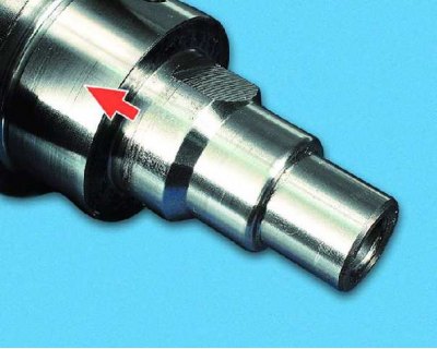
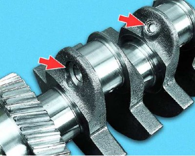
120. If there are deep scratches, scratches, nicks on the surfaces of the crankshaft on which the seals work, the crankshaft must be replaced.
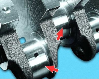
121. If there are minor scuffs, risks, scratches on the main and connecting rod journals, you need to grind them to the nearest repair size (in a specialized workshop). After that...
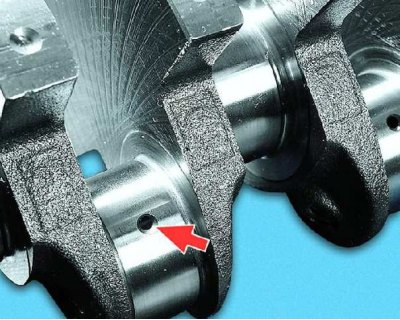
122....polish the journals and blunt the sharp edges of the chamfers of the oil passages with an abrasive cone. Then flush the crankshaft and blow out the oil passages with compressed air. The ovality and taper of all necks after grinding should not exceed 0.005 mm. After grinding the necks, install the bushings of repair sizes.
123. Measure the main and connecting rod journals of the crankshaft. If the wear or ovality of the necks exceeds 0.03 mm, they must be ground to the nearest repair size.
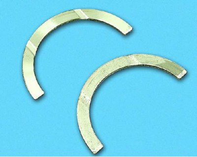
124. If on the working surfaces of the thrust half rings there are scores, risks and delaminations, replace the half rings. It is forbidden to carry out any fitting work on the half rings.
Selection of crankshaft liners
Nominal diameter of crankshaft journals, mm:
- indigenous 50.799-50.819
- connecting rod 47.830-47.850
The crankshaft journals can be ground to one of four repair sizes with a decrease in the nominal diameter of the journals, mm:
- first by 0.25 third by 0.75
- second by 0.5 fourth by 1.00
Nominal thickness of liners, mm:
- indigenous 1,824-1,831
- connecting rod 1.723-1.730
Inserts are also supplied as spare parts in four repair sizes, increased thickness, mm:
- first by 0.25 third by 0.75
- second by 0.5 fourth by 1.00
Clearances between liners and crankshaft journals, mm:
- for main bearings: nominal - 0.026-0.073, maximum allowable - 0.11;
- for connecting rod bearings: nominal - 0.02-0.07, maximum allowable - 0.1.
The runout of the crankshaft should be, mm:
- along the middle main journal and the seating surface under the drive gear of the oil pump - no more than 0.03;
- on the landing surface under the flywheel - no more than 0.04;
- on the seating surface under the pulleys and seals and under the balance shaft drive gear - no more than 0.05.
Dimensions of half rings supplied as spare parts: nominal - 2.31-2.36 mm and repair (enlarged by 0.127 mm) - 2.437-2.487 mm.
Axial clearance of the crankshaft: nominal - 0.06-0.26 mm, maximum allowable - 0.35 mm.
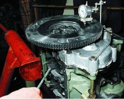
125. Measure the end clearance of the crankshaft. To do this, install the crankshaft and thrust washers in the cylinder block and tighten the bolts securing the main bearing caps. Install the flywheel. Fix the indicator so that its leg rests on the working surface of the flywheel (contact with clutch disc). Slide the crankshaft all the way down (from the indicator) and set the indicator arrow to zero. Slide the shaft back. The indicator will show the gap value. If the gap exceeds the maximum allowable, replace the thrust half rings.
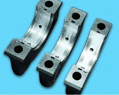
126. Check the main bearings. If they have cracks, scuffs, chipping, replace the liners. It is forbidden to carry out any adjustment work on the liners.

127. Thoroughly clean and flush the crankshaft oil passages. Wherein...
128.... it is not recommended to press out the plugs yourself (to do this, contact a specialist workshop).
129. Thoroughly clean the surfaces of the cylinder block from the remnants of old sealing gaskets. Check the block carefully. If cracks are found, replace the block complete with main bearing caps.
130. Check the tightness of the cylinder block cooling jacket. To do this, plug the hole for the water pump (install pump with gasket) and pour Antifreeze A-40 into the cooling jacket. If you notice a leak somewhere, then the block is leaky and needs to be replaced.
Explanation
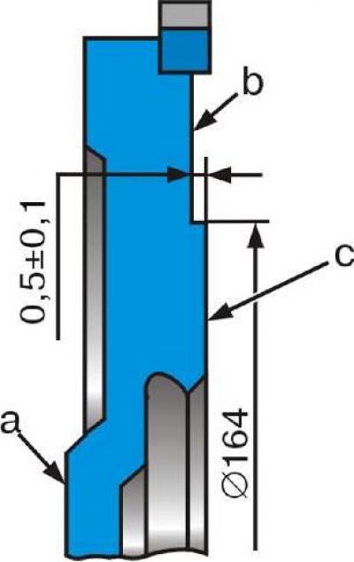
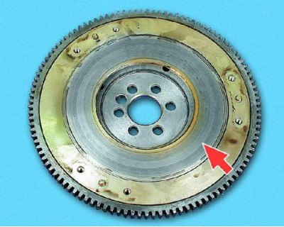
The non-flatness of the surface from the contact of the clutch driven disk should not exceed 0.05 mm.
The non-parallelism of the surface c of the contact of the clutch driven disk and the surface b for attaching the clutch relative to the surface a adjacent to the crankshaft flange should not exceed 0.1 mm.
The runout of the flywheel on surfaces b and c must not exceed 0.1 mm.
To remove deep scratches and scuffs, the surface from the flywheel can be machined, while the layer of metal removed should not exceed 1 mm. Simultaneously with surface c, it is necessary to machine surface b, keeping the size between them 0.5-0.1 mm. When turning, keep surfaces a, b and c parallel.
The ring gear on the flywheel must not rotate when a torque of 600 Nm is applied to it (60 kgf/m) and move in the axial direction when a force of 4000 N is applied to it (400 kgf).
131. Check up backlashes between loose leaves of radical bearings and necks of a cranked shaft. To do this, measure the diameter of the necks, and then the diameter of the main bearings, installing the covers with liners on the block and tightening them to the appropriate torques. Calculate clearance. If it exceeds the maximum allowable, the crankshaft must be ground to the next repair size. This work is recommended to be carried out in a specialized workshop.
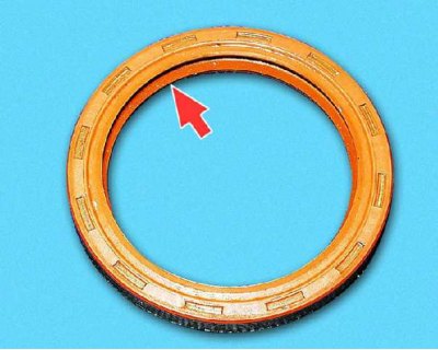
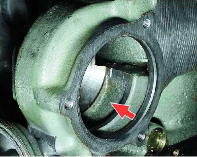
132. Check up a condition of a back epiploon of a cranked shaft. Seal with damage (cracks), wear of the working edge, which has lost its elasticity, replace.

133. The holder of the rear oil seal of the crankshaft must not have cracks, strong deformations of the mating surface to the cylinder block.
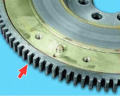
134. Check the condition of the flywheel ring teeth and replace the flywheel if damaged.
135. Replace or repair the flywheel if the mating surfaces of the clutch disc or...
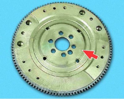
136.... the crankshaft flange has notches and burrs.
137. If tint colors are visible on the contact surface of the clutch disc (flywheel was overheated), then the ring gear on the flywheel may not be tight enough. This can be checked in a specialized workshop. A flywheel with a loose ring gear must be replaced.