
- key "at 13"
- screwdriver
Remove the air filter (see subsection 10.10.1.).
When installing the fuel pump, check and, if necessary, adjust its supply using gaskets. To do this, determine the protrusion of the pump pusher from the plane of the heat-insulating spacer, which should be 0.8–1.3 mm.
If the pump pusher protrudes less than the permissible one, then at high speeds or loads, fuel will be supplied to the carburetor in insufficient quantities. If the stem protrudes more than allowed, then excess fuel pressure will occur, which can lead to failure of the carburetor shut-off valve.
Spare parts are supplied with gaskets with a thickness of 0.27–0.33; 0.70–0.80 and 1.10–1.30 mm. A gasket with a thickness of 0.27–0.33 mm must be installed under the heat-insulating spacer.
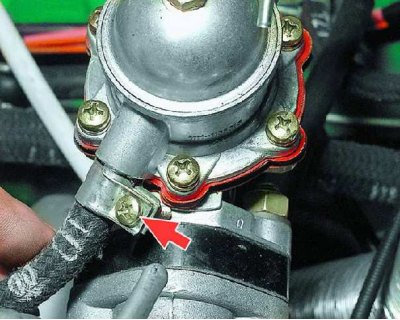
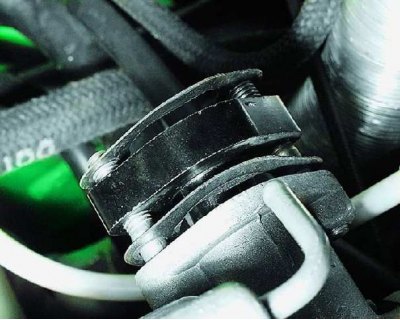
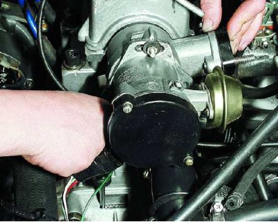
1. Loosen the clamp and disconnect the hose from the pump outlet. Place a rag under the pump nozzle.
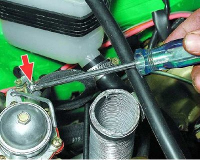
2. Loosen the clamp and disconnect the hose from the pump suction port.
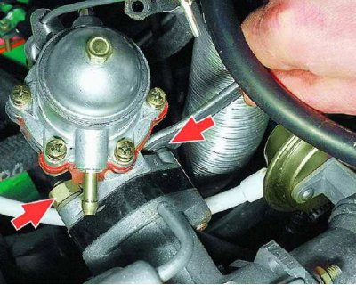
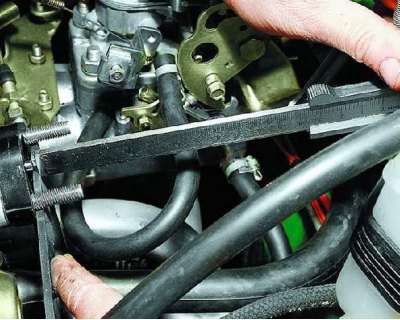
3. Loosen the two pump mounting nuts.

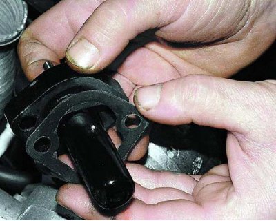
4. Carefully (not to damage the seal) remove the fuel pump.
5. Carefully remove the thermal spacer with stem, inner and outer gaskets. Replace damaged gaskets.
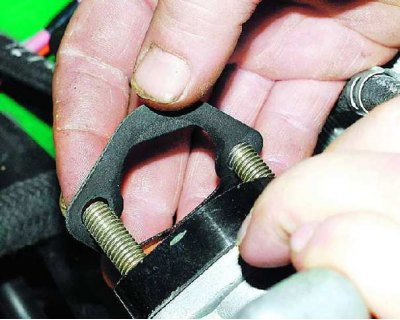
6. Install the heat-insulating spacer, placing a gasket under it (internal) 0.27–0.33 mm thick.
7. Pressing the pusher with your finger, slowly turn the crankshaft by the flywheel until you feel the minimum protrusion of the pusher.
8. Pressing the heat-insulating spacer, attach a metal ruler to its plane (so she doesn't bend) and measure the stem protrusion. Add to the resulting value the thickness of the ruler and...
9.... select the outer gasket so that after its installation, the protrusion of the stem is 0.8–1.3 mm (gasket set allowed).
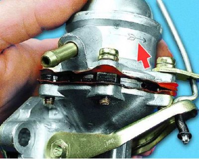
10. Install the pump in the reverse order of removal. In this case, the arrow indicating the direction of fuel movement should be directed towards the discharge fitting, to which the hose leading to the carburetor is connected.