




Fuel pump
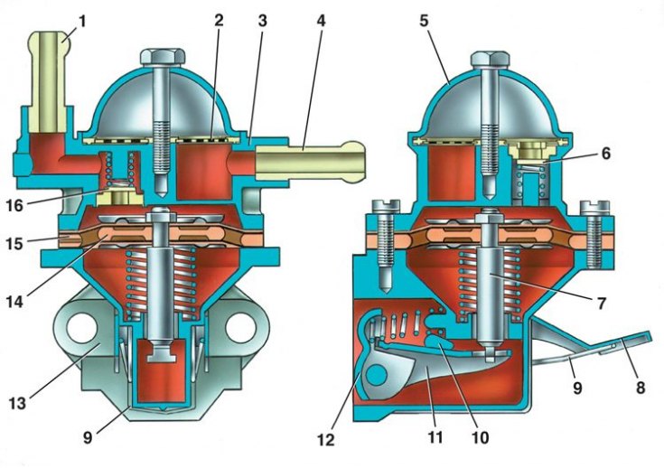
1 – discharge pipe; 2 – filter; 3 – body; 4 – suction pipe; 5 – lid; 6 – suction valve; 7 – pusher; 8 – manual fuel pumping lever; 9 – spring; 10 – cam; 11 – balance beam; 12 – lever for mechanical fuel pumping; 13 – bottom cover; 14 – internal spacer gasket; 15 – external spacer gasket; 16 – discharge valve
Circuit diagram for monitoring and adjusting the protrusion of the pump drive pusher
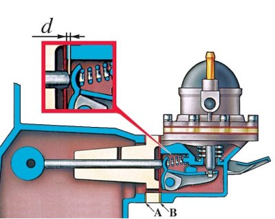
A – gasket thickness 0.27–0.33 mm; B – gasket thickness 0.70–0.80 mm; d – pusher protrusion
The fuel pump device is shown in Fig. Fuel pump.
Examination
Insufficient filling of the carburetor with gasoline may be due to a malfunction of the fuel pump, as well as clogged or damaged pipelines.
To find the cause of the malfunction, disconnect the hose from the discharge pipe 1 and use the lever 8 of the manual fuel pump to check whether fuel is supplied. If there is no fuel, then disconnect the hose from the suction pipe 4 and check whether a vacuum is created at the outlet of this pipe. If there is a vacuum, then the pipeline is faulty, and if not, then the pump is faulty.
Disassembly, cleaning and inspection of parts
1. To disassemble the pump, unscrew the cover mounting bolt 5, remove the cover and filter 2. Then unscrew the screws securing the housing to the bottom cover, separate them, remove the diaphragm assembly and spring.
2. Wash all parts with gasoline and blow with compressed air.
3. Check the integrity of the pump springs.
4. Check for valve sticking. Check the condition of the diaphragms. They should not be cracked or hardened.
5. After checking, replace all worn or damaged parts with new ones. Always replace the pump gaskets with new ones and lubricate them with a thin layer of grease before installation.
Installation
The pump installation diagram is shown in Fig. Diagram for monitoring and adjusting the protrusion of the pump drive pusher.
1. To properly install the fuel pump, use two of the three gaskets: A - 0.27-0.33 mm thick; B – thickness 0.70–0.80 mm; C – thickness 1.10–1.30 mm.
2. Install the heat-insulating spacer on the cylinder block, placing gasket A between them, and place gasket B on the plane mating with the pump. Measure the distance d using tool 67.7834.9506 (the minimum amount by which the pushrod protrudes, determined by slowly turning the crankshaft). If the dimension d is between 0.8 and 1.3 mm, then fix the pump to the engine. If d is less than 0.8 mm, replace gasket B with gasket A; if more than 1.3 mm, replace gasket B with gasket C. Check dimension d again and secure the pump to the engine.
3. There must always be a gasket A between the cylinder block and the heat-insulating spacer.